
Mechanism for changing the tilt of the backrest having regard to the seat of a chair

a technology for adjusting the seat and backrest, which is applied in the field of adjusting the seat of the chair, can solve the problems of large number of mutually movable components, the inability to change the seat position, and the complexity of the components

Active Publication Date: 2017-05-18
DONATI +2
View PDF12 Cites 7 Cited by
  • Summary
  • Abstract
  • Description
  • Claims
  • Application Information

AI Technical Summary

Benefits of technology

The invention introduces a solution for improving the comfort of a vehicle seat by tilting the backrest without using complex synchronizing mechanisms. The solution involves a covering element that can be raised at the front of the seat when the backrest is tilted, providing greater comfort for the user. The covering element is deformed by a lever arm that is rotated by the backrest frame, which ensures that the covering element stays connected to the base frame. The lever arm is designed to reversely deform the covering element when it reaches its maximum or minimum rotation positions. This solution is simpler and more cost-effective than known synchronizing mechanisms, while still providing a comfortable experience for the user. In a preferred embodiment, the lever arm has two cranks connected by a crossbar, where the front crank raises more than the rear crank when the backrest is tilted from its minimum to maximum tilt, improving the user's comfort.

Problems solved by technology

However, the adjusting mechanisms used in such a chairs do not allow the position of the seat to be changed when the tilt of the backrest changes in order to prevent the user from experiencing an uncomfortable feeling of “sinking” in the seat or moving toward the front edge of the latter, in various backrest tilts.
However, the drawback of the herein described synchronizing means is their complexity and the use of a large number of mutually movable components.
Thus, for example, the aforementioned adjusting mechanism of the synchronizing type, is not very suitable for traditional chairs having four fixed side legs, since these have to be made so as to limit the number of components and their structural and operational complexity, for allowing to be constructional simple and therefore to be cost effective.

Method used


Image

  • Mechanism for changing the tilt of the backrest having regard to the seat of a chair
  • Mechanism for changing the tilt of the backrest having regard to the seat of a chair
  • Mechanism for changing the tilt of the backrest having regard to the seat of a chair

Examples


Embodiment Construction

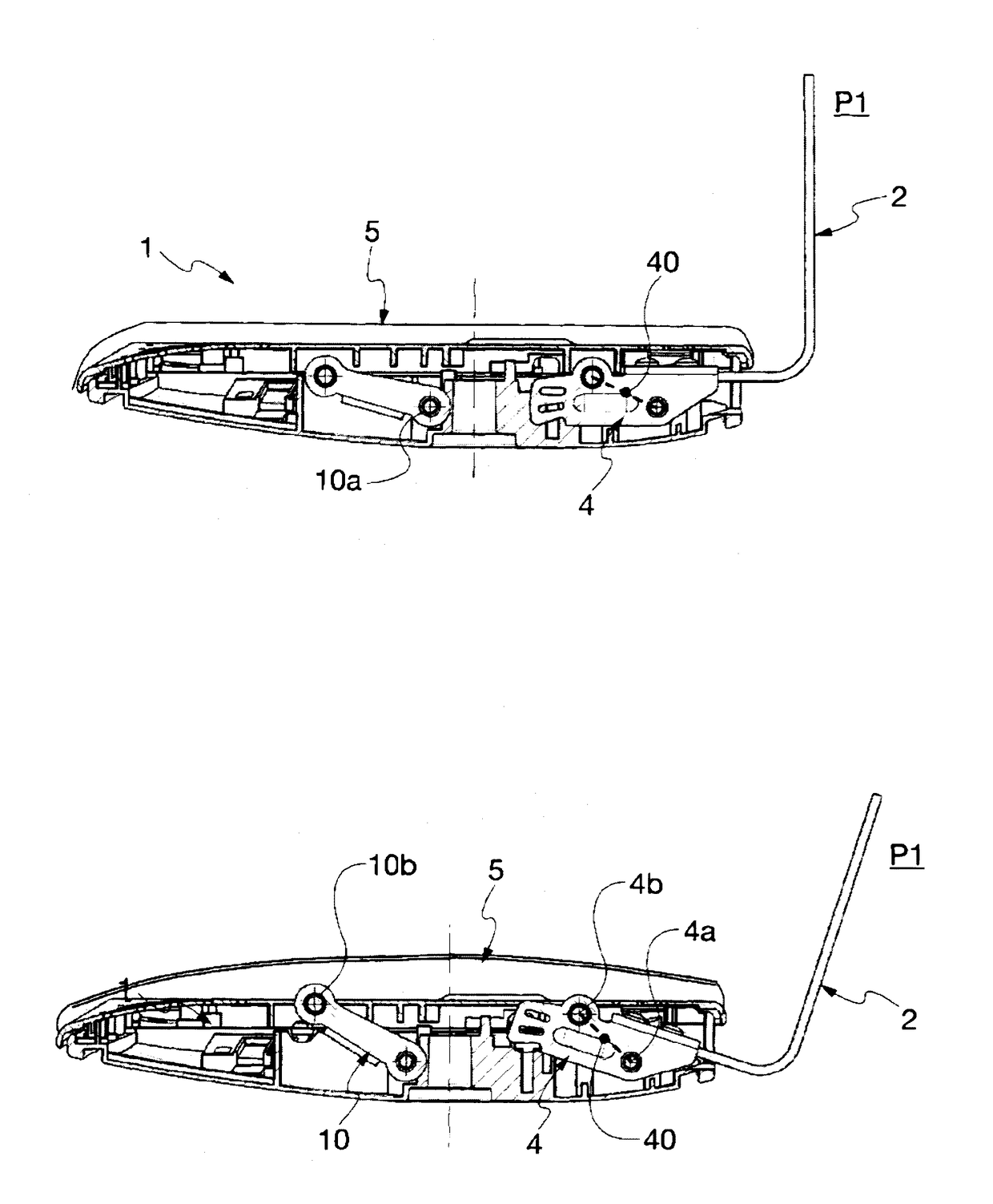
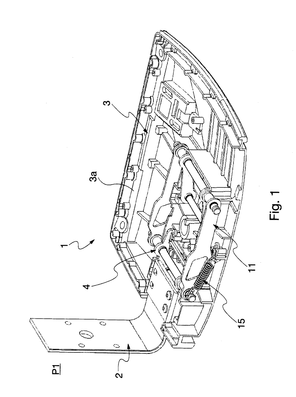
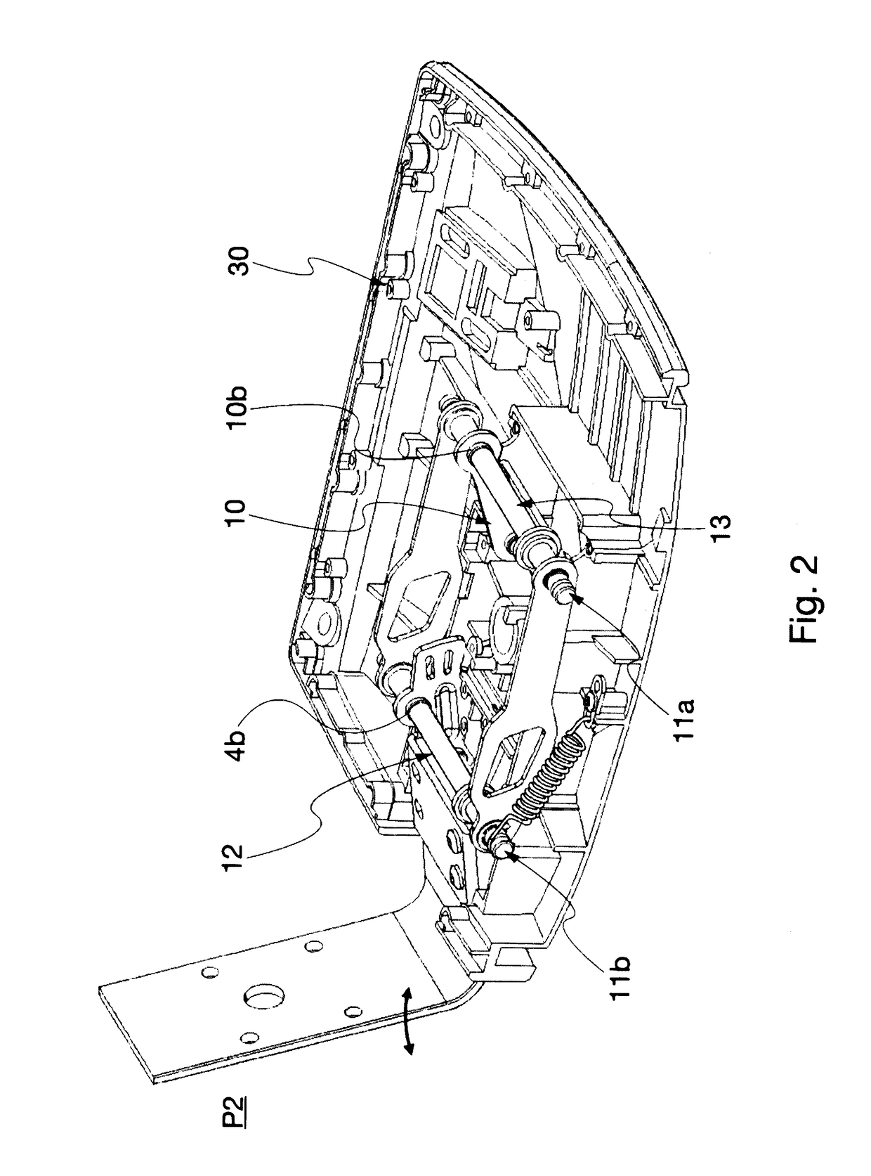
[0031]Particularly referring to the attached figures, according to a particular aspect of the present invention a mechanism for adjusting the seat of a chair when the tilt of the backrest with respect to such a seat changes, is referred to with the numeral 1.

[0032]Figures show this mechanism 1 comprising a backrest frame 2 allowing a preferably padded backrest (not shown herein) to be made integral therewith according to known technique, a base frame 3 having a seat combined therewith and the backrest frame 2 being rotatably constrained thereto by means of a pin 4a, and a covering element 5 forming at least part of said seat and being stably combined with the base frame 3.

[0033]The backrest frame 2 is shaped in a known manner, for example through suitable limit stops, to be able to tilt by rotating around the axis of the pin 4a, between a position (P1) of minimum tilt—shown in FIG. 1—and a position (P2) of maximum tilt—shown in FIG. 2—with respect to the base frame 3, and therefore ...


PUM


Abstract

A mechanism for adjusting the seat of a chair as a result of changing the tilt of the backrest with respect to the seat is provided. The mechanism has a backrest frame and a base frame, as well as a covering element stably combined with the base frame and forming part of the seat. The backrest frame is rotatably constrained to the base frame around a respective rotation axis and tilting with respect to the seat between a position (P1) of minimum tilt and a position (P2) of maximum tilt. Advantageously, the covering element is partially elastically deformable, with the mechanism having deforming means operated by the backrest frame in order to reversibly deform, in the vertical direction, when the covering element as a function of the tilt angle with backrest frame has reached with respect to the position (P1) of minimum tilt.

Description

FIELD OF THE INVENTION[0001]The present invention relates to a mechanism for adjusting the seat of a chair when the tilt of the backrest changes with respect to the seat itself.[0002]In particular, the mechanism in question is of the type provided with a backrest frame, a base frame having the seat stably constrained thereto and a lever, or another similar raising mechanism, operatively interposed between the seat and the base frame itself, in order to directly or indirectly transmit the tilting movement of the backrest to the seat, or vice versa.BACKGROUND ART[0003]Chairs comprising a backrest frame, a fixed base frame having the seat constrained thereto and a mechanism for adjusting the seat when the tilt of the backrest changes with respect to the seat itself, are known in the art.[0004]Usually, a covering element made of various materials is placed above the seat and can fully cover the seat on which, once upholstered, the user will sit.[0005]However, the adjusting mechanisms us...

Claims


Application Information

Patent Timeline
Patent Type & Authority Applications(United States)
IPC IPC(8): A47C1/032A47C7/14
CPCA47C7/14A47C1/03261A47C1/024A47C1/03255A47C7/004
Inventor DONATI, ARMANDOLIEVORE, ALBERTO
Owner DONATI
Learn More