Transmission system particularly useful as a continuously variable transmission

a transmission system and continuously variable technology, applied in the direction of gearing elements, belts/chains/gearrings, portability lifting, etc., can solve the problems of wear, noise, noise and other problems, each method suffers from a number, and achieves the effect of efficient establishment of a non-slip coupling

Inactive Publication Date: 2017-05-25
CVTRON LTD
View PDF0 Cites 2 Cited by
  • Summary
  • Abstract
  • Description
  • Claims
  • Application Information

AI Technical Summary

Benefits of technology

[0005]One object of the present invention is to provide a transmission system including two transmission members which may be selectively coupled and decoupled from each other in an efficient manner. Another object of the invention is to pr

Problems solved by technology

The main engineering challenge in such CVT systems is the sliding of the driving member on the driven member.
Such sliding cre

Method used


Image

  • Transmission system particularly useful as a continuously variable transmission
  • Transmission system particularly useful as a continuously variable transmission
  • Transmission system particularly useful as a continuously variable transmission

Examples


Embodiment Construction

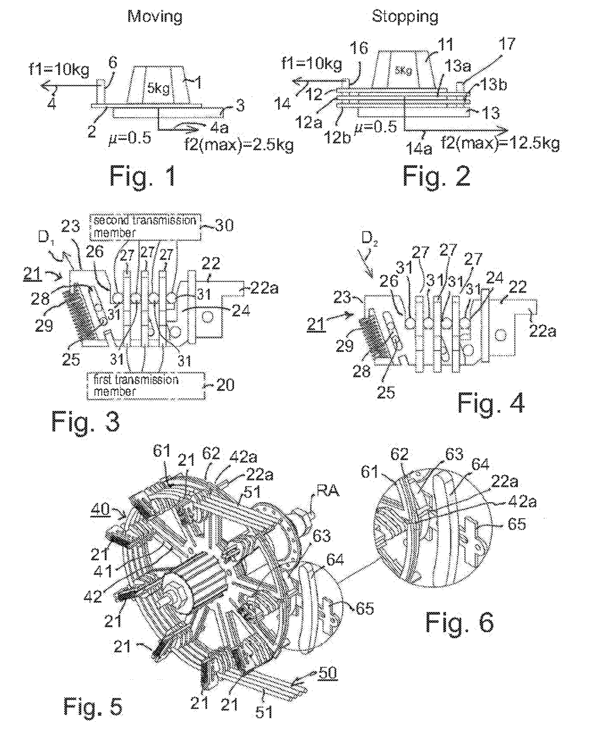
[0032]As indicated earlier, the present invention relates to a transmission system which may be efficiently controlled to establish a non-slip coupling between the two transmission members, or to decouple the two transmission members from each other, which transmission system is particularly useful for producing an efficient CVT system. Before describing several preferred embodiments of the invention as illustrated in the accompanying drawings, it will be helpful first to describe the diagrams of FIGS. 1 and 2 illustrating a basic concept involved in the present invention.

[0033]FIG. 1 illustrates a weight 1 of 5 Kg placed on a surface 2 attached to an object 6 being pulled to the left by a vector force 4 of 10 Kg. Surface 2 slides over a single stationary surface 3, with a friction coefficient (.mu.) of 0.5. Clearly, the pulling force 4 is sufficient to move object 6 over surface 2. The friction force 4a, which is approximately 2.5 Kg (5 Kg.times.0.5), cannot prevent surface 2 from ...


PUM


Abstract

A transmission system includes: first and second transmission members to be selectively coupled to each other or decoupled from each other. The first transmission member includes at least one gripping device having a plurality of spaced gripping elements, and the said second transmission member includes a plurality of coupling elements receivable in an interleaved manner between the gripping elements of the gripping device. The gripping elements of the gripping device being displaceable by a lateral compressive force (a) to displace them towards each other to firmly grip the coupling elements of the second transmission member and thereby to establish a non-slip coupling between the two transmission members; and (b) away from each other to decouple the two transmission members from each other. In a described preferred embodiment, the first transmission member includes a pair of rotatable conical members over which the second transmission member is wound, the conical members being movable towards and away from each other to radially displace the second transmission member such as to define a continuously variable transmission.

Description

CROSS-REFERENCE TO RELATED APPLICATION[0001]This is a divisional application claiming priority from U.S. patent application Ser. No. 12 / 086,185 filed 17 Sep. 2009.FIELD AND BACKGROUND OF THE INVENTION[0002]The present invention relates to transmission systems, for selectively coupling two transmission members to each other. The invention is particularly useful in a continuously-variable transmission system, and is therefore described below with respect to that application.[0003]Continuously variable transmissions (CVTs) are well known in the art of mechanical engineering as a means for the continuous variation of the transmission ratio between a driving member and a driven member. A common method of CVT involves conical wheels and flexible belts.[0004]The main engineering challenge in such CVT systems is the sliding of the driving member on the driven member. Such sliding creates wear, loss of energy, noise and other problems. The most efficient way of reducing this sliding is by in...

Claims


Application Information

Patent Timeline
IPC IPC(8): F16H9/10F16H9/16F16H9/24F16H55/54F16H55/56
CPCF16H9/10F16H55/54F16H9/16F16H9/24F16H55/56
Inventor SIMAN-TOV, RAN
Owner CVTRON LTD
Why Eureka
Try Eureka