Concealed Carry Firearm Assembly, System and Method

a concealed carry and firearm technology, applied in the field of concealed carry firearm assembly, system and method, can solve the problems of affecting the speed of access to the firearm for use, the use of bulky concealment devices,

Inactive Publication Date: 2017-05-25
NELSON SCOTT
View PDF2 Cites 4 Cited by
  • Summary
  • Abstract
  • Description
  • Claims
  • Application Information

AI Technical Summary

Benefits of technology

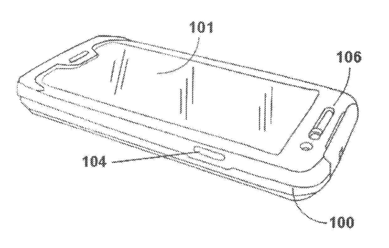
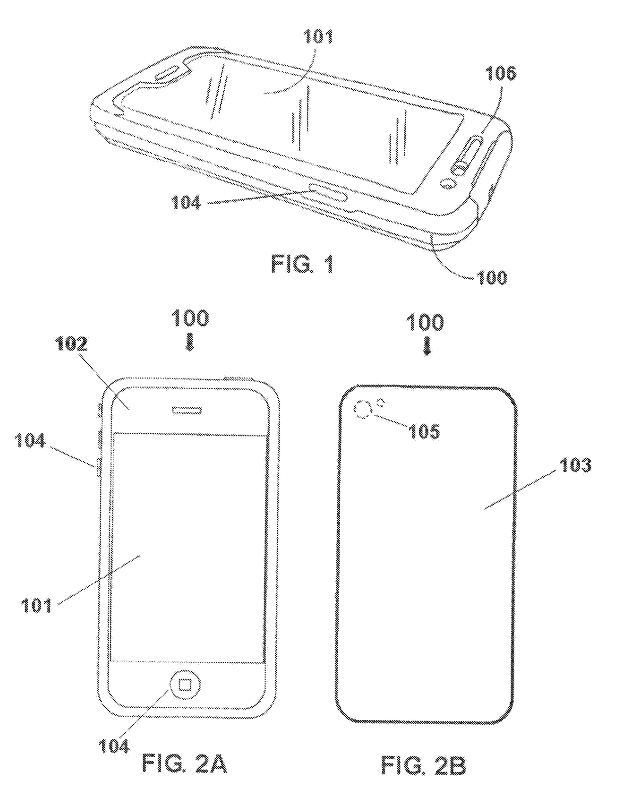
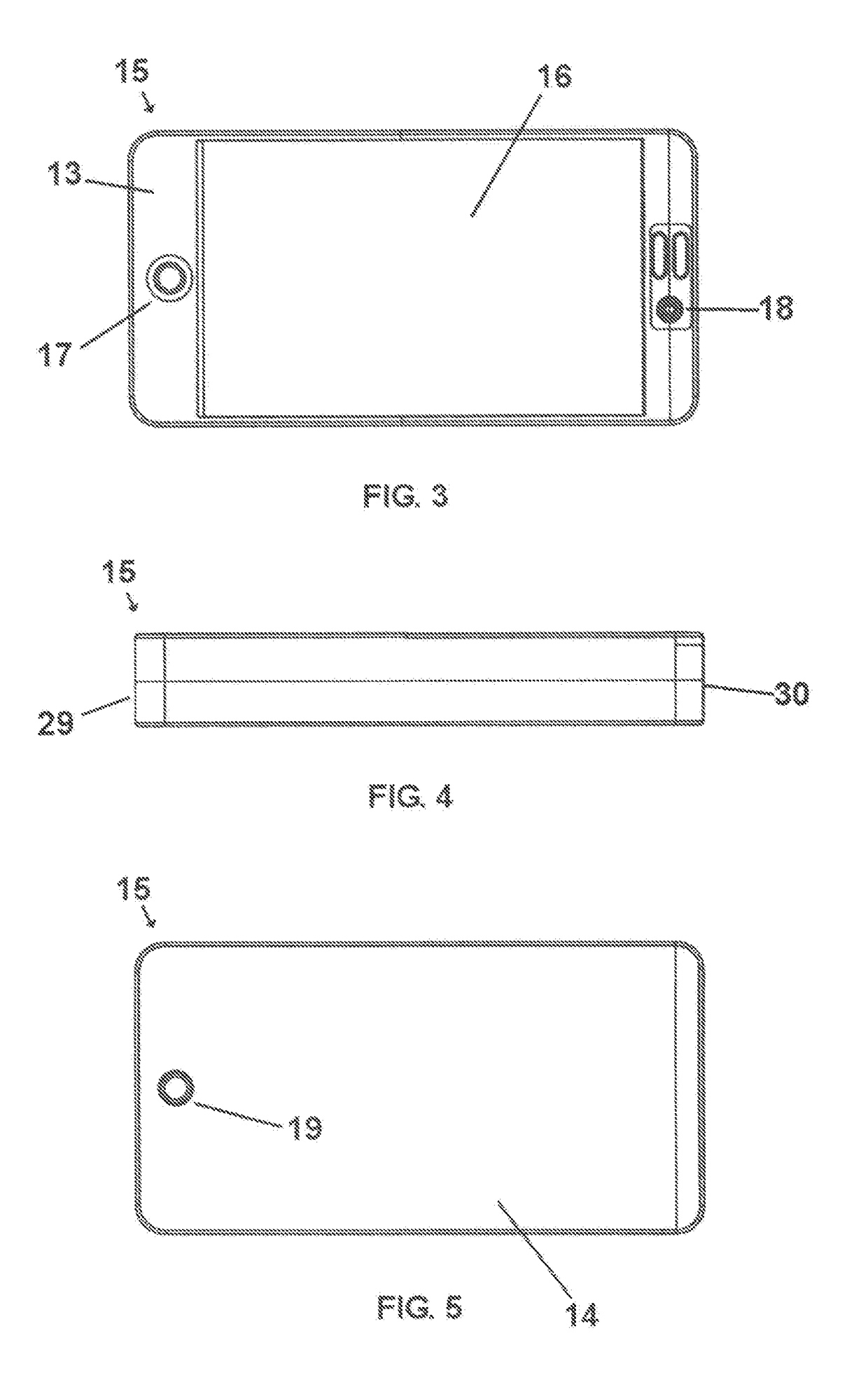
[0075]Turning to the simplified embodiment as illustrated in FIGS. 3-7, in one aspect the invention may comprise a system including a housing, also referred to herein as an outer case assembly or “outer case”15, and a corresponding firearm 25 effective to be inserted within the outer case 15 in a concealed manner and also effective to be withdrawn from the outer case 15 as desired. As shown, the front side 13 and the back side 14 of the outer case 15 may include one or more features as described above. For example, the front side 13 may include what may appear to an ordinary observer as a touch screen 16, a manual push button 17, a microphone 18 and a camera lens 19. In this embodiment, the outer case 15 suitably includes a closed first end 29 and a second end defined by a closeable opening 30 or outlet for the firearm 25, although it is contemplated that an opening may be disposed along a side of the outer case 15 rather than at an end of the outer case 15. In one embodiment, the touch screen 16 may be provided as a substantially black glossy surface similar as a touch screen of an electronic mobile device in an OFF position or SLEEP position. In another embodiment, the touch screen 16 may include what appears to be one or more program or function icons disposed across the touch screen 16 similar as an electronic mobile device set at an ON position. In another embodiment, the outer case 15 may be provided as a single piece manufacture. In another embodiment, the outer case 15 may be provided in multiple parts or sections for assembly / disassembly. For example, one suitable outer case 15 may include a front side member and a back side member similar as outer protective cases for mobile electronic devices that may be snap-fit together or adhered together for permanent attachment.
[0076]With attention to FIGS. 8-15, the opening 30 of the outer case 15 may be provided with a dual flap type cover assembly including opposing flap members 31, 32 moveable between an open position (see FIGS. 8-11) and a closed position (see FIGS. 12-15). The flap members 31, 32 may be attached to the outer case 15 as desired. In one embodiment, the flap members 31, 32 may be attached to the outer case 15 in a biased manner enabling the flap members 31, 32 to rest in a closed position as shown in FIGS. 12-15 (1) until a firearm 25 is ejected out from the outer case 15 whereby the flap members 31, 32 are forced open by the firearm 25 or (2) until the flap members 31, 32 are manually opened, e.g., when inserting a firearm 25 into the outer case 15 for concealment purposes. In another embodiment, the flap members 31, 32 may be attached to the outer case 15 via elongated spring-biased hinges or the equivalent. In another embodiment, the flap members 31, 32 may be attached to the outer case 15 via a series of spring biased strap hinges, swing door fittings, and combinations thereof. In one particular embodiment, the flap members 31, 32 may be attached to the outer case 15 via elongated spring-biased piano hinges. In still another embodiment, the non-biased flap members 31, 32 may be hingedly attached to the outer case 15 and held in a closed position via one or more snap fittings, releasable locks, or via a tight flush fitting with the coverable opening 30 of the outer case 15. In another embodiment, the flap members 31, 32 may be fixed in a closed position against the outer case 15 via magnetism, e.g., one or more magnets disposed along the flap members 31, 32 corresponding with metal inlays along outer case 15 or vice versa.
[0077]In still another embodiment, the flap members 31, 32 may be double biased in either direction. For example, if a flap member is less than about half-way open, the flap member may be urged to a closed position. Likewise, if the flap member is more than about half-way open, the flap member may be suitably urged toward an open position. Regardless the mechanism employed, the flap members 31, 32 of FIGS. 8-15 are suitably constructed from one or more rigid type materials effective for opening and closing as described above.
[0078]In still another embodiment as illustrated in FIGS. 16-18, the coverable opening 30 may include one or more flexible members 34, 35 fixed to the outer case 15 in a non-hinged arrangement whereby the one or more flexible members 34, 35 are operationally configured to flex inward and outward (see Directional Arrows A and B) as a firearm 25 passes there between in either direction. In one suitable embodiment, the one or more flexible members 34, 35 as shown in FIGS. 16-18 may be constructed from rubber, leather, and combinations thereof. Suitable rubbers may include, but are not necessarily limited to silicon rubber, neoprene, butyl rubber, and combinations thereof.
[0079]In still another embodiment as illustrated in FIGS. 19-24, the opening 30 of the outer case 15 may include a removable cap 37 type member operationally configured to (1) conceal a firearm 25 housed within the outer case 15 from view when the removable cap 37 is mated to the coverable opening 30 and (2) expose the inner surface 40 of the outer case 15, and firearm 25 housed therein, when the removable cap 37 is separated apart from the outer case 15. The cap 37 may be secured to the outer case 15 as desired, suitably, in a manner effective to retain the cap 37 in a mated position with the coverable opening 30 during system 10 operation. As understood by the skilled artisan, the cap 37 may include a rim 38 with an outer surface operationally configured to mate flush with the perimeter of the inner surface of the coverable opening 30 in a slip-on manner.
[0080]One advantageous feature of the present system 10 involves providing an outer case 15 having an inner surface 40 configuration for use with a particular firearm 25. For example, the system 10 may employ an inner surface 40 configured to receive a novel firearm characterized by distinct ornamental surface features. In such embodiment, the outer case 15 is intended for operation solely with the corresponding firearm 25. In another embodiment, the outer case 15 may include an inner surface 40 operationally configured to provide a suitable system 10 for operation with a known commercially available firearm 25. In still another embodiment, the outer case 15 may include an inner surface 40 operationally configured to work with a plurality of known commercially available firearms 25. The first variation of the system 10 described in this paragraph may be referred to herein as an “Original Model” of the system 10 and the latter two variations of the system 10 may be referred to as “Custom Models” of the system 10. As such, an Original Model may include a firearm 25 size and shape as desired or as otherwise required. As understood by the skilled artisan, the size and shape of the firearm 25 of the system 10 dictates the size of the outer case 15.

Problems solved by technology

Unfortunately, such attempts include using objects having the appearance of mobile electronic devices as a facade for known firearms and holsters, which results in bulky concealment devices and / or devices that hinder speedy access to the firearm for use.

Method used


Image

  • Concealed Carry Firearm Assembly, System and Method
  • Concealed Carry Firearm Assembly, System and Method
  • Concealed Carry Firearm Assembly, System and Method

Examples


example 1

[0102]In a first non-limiting embodiment of the system 10 as shown in FIGS. 47-52, an outer case 15 and corresponding firearm 25 may be provided according to the following dimensional ranges:

[0103]D1: about 10.2 cm to about 17.8 cm (about 4.0 inches to about 7.0 inches);

[0104]D2: about 1.7 cm to about 3.2 cm (about 0.65 inches to about 1.25 inches);

[0105]D3: about 6.4 cm to about 8.9 cm (about 2.5 inches to about 3.5 inches);

[0106]D4: about 9.9 cm to about 17.5 cm (about 3.9 inches to about 6.9 inches);

[0107]D5: about 1.5 cm to about 3.1 cm (about 0.60 inches to about 1.20 inches);

[0108]D6: about 6.1 cm to about 8.6 cm (about 2.4 inches to about 3.4 inches).

example 2

[0109]In a second non-limiting embodiment, a system 10 including an outer case 15 and firearm 25 for right handed use as shown in FIG. 40 is provided. The system 10 further includes a holster secured to the back of the outer case 15, the holster having a clip for attaching to the belt 410 around the waist of a user 411 as shown in FIGS. 53 and 54. In operation, a user 411 places the firearm 25 inside the outer case 15 in a concealed loaded position either before or after attaching the outer case 15 to his / her belt 410 along the right side of his / her waist. When access to the firearm 25 is desired, the user 411 activates the ejection assembly of the outer case 15 by pressing inward on the release member 50, which directs the firearm 25 to a non-concealed position as shown in FIG. 54. Once the firearm 25 is in a non-concealed position, the user 411 may grab the firearm with his / her hand for operation of the firearm 25.


PUM


Abstract

The application is directed to a mobile firearm concealment system including a housing for concealing a corresponding firearm therein. The housing may include an outer appearance, shape and size of a mobile electronic device. The housing may also include an inner surface operationally configured to hold the firearm in a concealed position within the housing and to also direct the firearm to a non-concealed position. The housing and firearm may also cooperate in a manner effective to dictate the non-concealed position of the firearm.

Description

CROSS-REFERENCE TO RELATED APPLICATIONS[0001]The application is entitled to the benefit of the filing date of the prior filed provisional application No. 62 / 259,925, filed on Nov. 25, 2015.STATEMENT REGARDING FEDERALLY SPONSORED RESEARCH OR DEVELOPMENT[0002]Not applicable.FIELD OF THE APPLICATION[0003]The application relates generally to the concealment of a firearm on a person.BACKGROUND[0004]Concealed carry handgun laws typically require carrying a firearm without brandishing the firearm. The most common ways of carrying a concealed firearm have included using hip holsters, crossdraw holsters, shoulder holsters, ankle holsters and boot clips, all of which are suitably concealed by a user's clothing and / or apparel. Other persons simply place a firearm in his / her pocket, purse or wallet. With the advent of mobile electronic devices such as tablet computers and smart phones, attempts have been made to incorporate the concealment of firearms using this new technology. Unfortunately, s...

Claims


Application Information

Patent Timeline
Patent Type & Authority Applications(United States)
IPC IPC(8): F41C9/02H04B1/3888
CPCH04B1/3888F41C9/02F41C33/0272
Inventor NELSON, SCOTT
Owner NELSON SCOTT
Why Eureka
Try Eureka