Fault detection methods and systems

a technology of fault detection and fault detection methods, applied in the direction of program control, testing/monitoring control systems, instruments, etc., can solve problems such as current fault detection methods, wear, and prone to fault or failure of gas turbine engines, along with their attendant sensors

Active Publication Date: 2017-05-25
RAYTHEON TECH CORP
View PDF5 Cites 8 Cited by
  • Summary
  • Abstract
  • Description
  • Claims
  • Application Information

AI Technical Summary

Benefits of technology

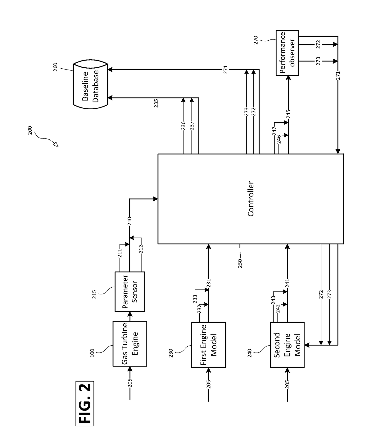
[0004]In various embodiments, the present disclosure provides methods and systems of detecting faults in gas turbine engines. A system for fault detection in a gas turbine engine may comprise a parameter sensor in communication with a controller, engine models in communication with the controller configured to simulate an operational gas turbine engine and produce estimated parameter values, a performance observer in communication with the controller configured to produce tuner values, and a tangible, non-transitory memory in communication with the controller providing the controller with instructions to perform operations. An article of manufacture may also comprise a tangible, non-transitory memory in communication with a controller, causing the controller to perform operations. Such operations may comprise receiving actual parameter values from the parameter sensor at different times, receiving estimated parameter values from the engine models, calculating parameter differences based on differences between the estimated and actual parameter values, and reporting parameter differences at different times to a baseline database for the gas turbine engine, if the parameter differences are not above a predetermined detection threshold. The controller operations may further comprise receiving tuning values at different times from the performance observer configured to adjust one of the engine models, reporting the tuning values to the baseline database, and adjusting one of the engine models using the tuning values. The controller operations may further comprise determining whether a fault has occurred in the gas turbine engine based on comparisons between the parameter differences, between the difference in the tuning values, and comparisons of the parameter differences and tuning values with their respective baseline values. The method may further comprise identifying the fault by calculating a first parameter difference fault signature based on the difference between the first parameter difference baseline and a first parameter difference with a highest quality number from the current aircraft flight, and comparing the fault signature with a fault s...

Problems solved by technology

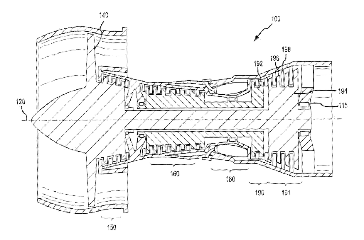
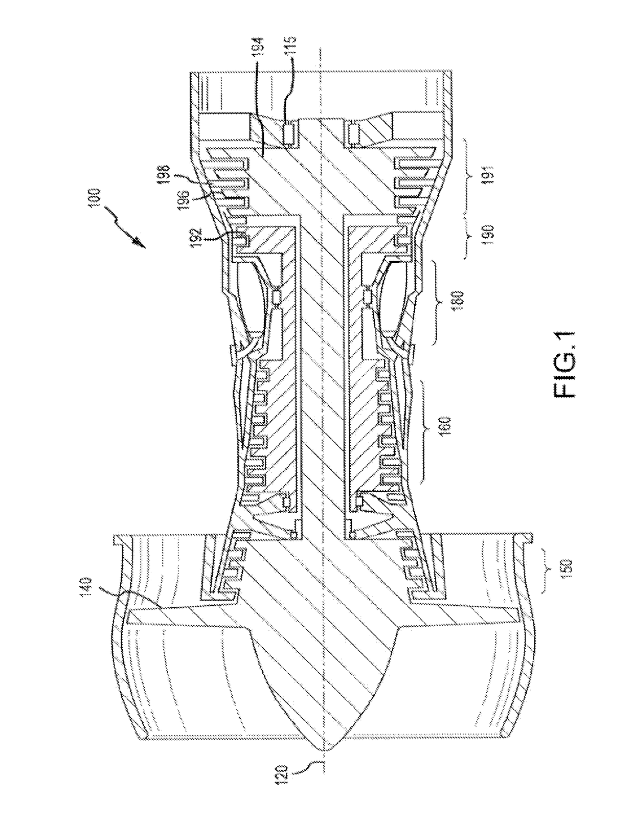
All these components of the gas turbine engine, along with their attendant sensors, wear over time and may be prone to fault or failure.
Current fault detection methods are confined to off-board analysis of snapshot data av...

Method used


Image

  • Fault detection methods and systems
  • Fault detection methods and systems
  • Fault detection methods and systems

Examples


Embodiment Construction

[0016]The detailed description of various embodiments herein makes reference to the accompanying drawings, which show various embodiments by way of illustration. While these various embodiments are described in sufficient detail to enable those skilled in the art to practice the disclosure, it should be understood that other embodiments may be realized and that logical, chemical, electrical, and mechanical changes may be made without departing from the spirit and scope of the disclosure. Thus, the detailed description herein is presented for purposes of illustration only and not of limitation.

[0017]For example, the steps recited in any of the method or process descriptions may be executed in any order and are not necessarily limited to the order presented. Furthermore, any reference to singular includes plural embodiments, and any reference to more than one component or step may include a singular embodiment or step. Also, any reference to attached, fixed, connected, or the like may...


PUM


Abstract

The present disclosure provides methods, systems, and computer-readable media for the fault detection and identification in an aircraft that may occur in real time during a flight, or any time the aircraft is operating. For example, a controller may receive and calculate various parameter values at various times during an aircraft flight, and compare those values to baseline values in order to determine if a fault has occurred. Additionally, the controller may identify a fault that has occurred by comparing a calculated fault signature value with a fault signature database comprising fault signatures and their associated faults.

Description

FIELD OF THE DISCLOSURE[0001]The present disclosure relates to fault detection systems and methods, and more particularly, to detecting engine module and subsystem faults and failures in gas turbine engines.BACKGROUND OF THE DISCLOSURE[0002]Gas turbine engines typically comprise a compressor module, a combustor module, and a turbine module, along with subsystems and accessories to control cooling, air bleed, variable geometry, etc. All these components of the gas turbine engine, along with their attendant sensors, wear over time and may be prone to fault or failure. Current fault detection methods are confined to off-board analysis of snapshot data averaged over stable flight conditions during steady-state operation of an engine. Additionally, such methodology only allows fault detection and identification after a suitable amount of flight data has been captured and analyzed.SUMMARY OF THE DISCLOSURE[0003]In various embodiments, the present disclosure provides methods, systems, and ...

Claims


Application Information

Patent Timeline
IPC IPC(8): G05B19/406
CPCG05B2219/31356G05B19/406G05B23/0254G05B23/0275G05B17/02
Inventor VOLPONI, ALLAN J.TANG, LIANG
Owner RAYTHEON TECH CORP
Why Eureka
Try Eureka