Vehicle display control apparatus

a technology for controlling apparatus and vehicles, applied in the field of vehicles, can solve the problems that the driver who sees the illusion image cannot help but behave instinctively in a desirable manner

Active Publication Date: 2017-06-01
DENSO CORP
View PDF9 Cites 30 Cited by
  • Summary
  • Abstract
  • Description
  • Claims
  • Application Information

AI Technical Summary

Benefits of technology

[0010]Hence, by displaying an object which does not actually exist on a road under circumstances where a predetermined condition is satisfied as an illusion image when the predetermined condition is satisfied, the driver who sees the illusion image cannot

Problems solved by technology

Hence, by displaying an object which does not actually exist on a road under circumstances where a predetermined condition is satisfied as an illusion image when the predetermined condition is

Method used


Image

  • Vehicle display control apparatus
  • Vehicle display control apparatus
  • Vehicle display control apparatus

Examples


first embodiment

[0037](Schematic Configuration of Drive Assist System 100)

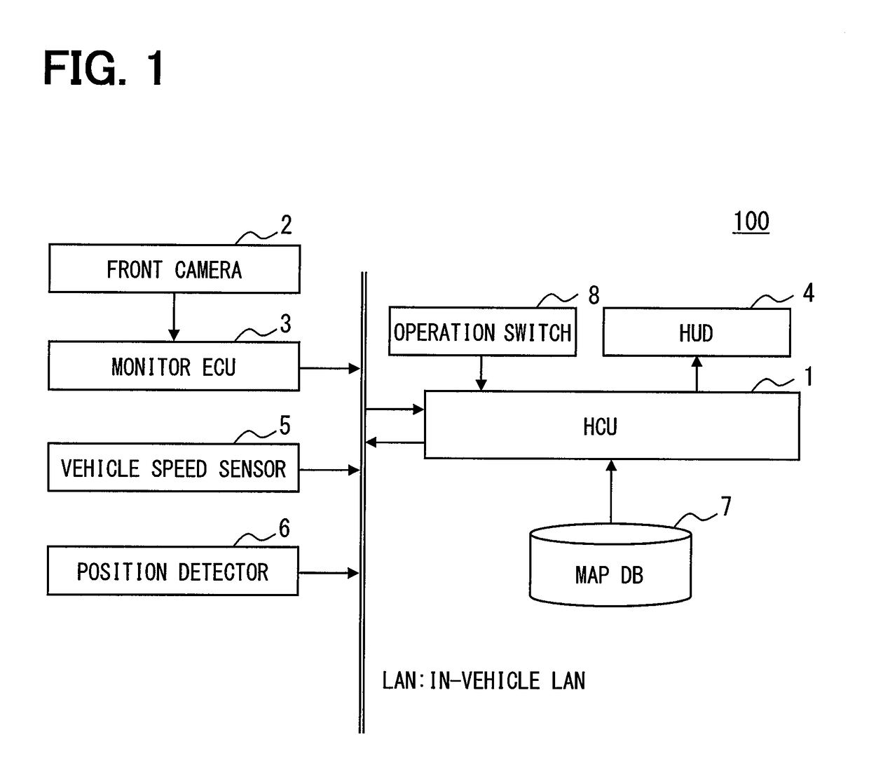
[0038]FIG. 1 is a view showing an example of a schematic configuration of a drive assist system 100 to which a vehicle display control apparatus of the present disclosure is applied. As is shown in FIG. 1, the drive assist system 100 includes an HCU (Human Machine Interface Control Unit) 1, a front camera 2, a monitor ECU 3, a HUD (Head-Up Display) 4, a vehicle speed sensor 5, a position detector 6, a map database (DB) 7, and an operation switch group 8. For example, the HCU 1 is connected to the monitor ECU 3, the HUD 4, and the vehicle speed sensor 5 via an in-vehicle LAN. Hereinafter, a vehicle equipped with the drive assist system 100 is referred to as the subject vehicle (also referred to as an own vehicle).

[0039]The front camera 2 is installed to the subject vehicle and captures an image of a region spreading ahead of the subject vehicle within a predetermined angle range. The front camera 2 is set with an optical axis ...

second embodiment

[0110]It should be appreciated that the present disclosure is not limited to the above embodiment, and a second embodiment in the following is also included in the technical scope of the present disclosure. Hereinafter, the second embodiment will be described.

[0111]A drive assist system 200 of the second embodiment is different from the drive assist system 100 of the first embodiment in a configuration of an illusion image to be displayed. The drive assist system 200 of the second embodiment is also different from the drive assist system 100 of the first embodiment in that an illusion image is displayed when a subject vehicle comes near a point at which the subject vehicle should slow down or should stop before proceeding instead of displaying an illusion image when the subject vehicle exceeds a speed limit value. Except for the two differences specified above, the drive assist system 200 of the second embodiment is the same as the drive assist system 100 of the first embodiment.

[01...

third embodiment

[0198]It should be appreciated that the present disclosure is not limited to the embodiments described above and a third embodiment in the following is also included in the technical scope of the present disclosure. Hereinafter, the third embodiment will be described.

[0199]A drive assist system 300 of the third embodiment is different from the drive assist system 100 of the first embodiment in a manner in which an illusion image is displayed. Also, the drive assist system 300 of the third embodiment is different from the drive assist system 100 of the first embodiment in that an illusion image is displayed when a subject vehicle reaches a tunnel where the subject vehicle should slow down instead of displaying an illusion image when the subject vehicle exceeds a speed limit value. Except for the two differences specified above, the drive assist system 300 of the third embodiment is the same as the drive assist system 100 of the first embodiment.

[0200](Schematic Configuration of Drive...


PUM


Abstract

A vehicle display control apparatus mounted on a vehicle includes a display control portion that controls a head-up display device displaying an image by superimposing the image on a view visible to a driver of the vehicle through a windshield of the vehicle, and a condition determination portion that determines whether a condition under which the vehicle should slow down is satisfied. The display control portion causes, based on a determination of the condition determination portion that the condition is satisfied, the head-up display device to display an object that does not actually exist on a road under circumstances where the condition is satisfied, as an illusion image that produces an optical illusion appearing that a road surface viewed from the driver flows faster than an actual speed in an opposite direction to a travel direction by superimposing the illusion image on the view.

Description

CROSS-REFERENCE TO RELATED APPLICATIONS[0001]The present application is based on Japanese Patent Application No. 2014-73788 filed on Mar. 31, 2014, the disclosure of which is incorporated herein by reference.TECHNICAL FIELD[0002]The present disclosure relates to a vehicle display control apparatus causing an image to be displayed on a windshield by using a head-up display device.BACKGROUND ART[0003]Conventionally, a head-up display device (hereinafter, abbreviated to HUD) displays an image by superimposing the image on a view visible to a driver of a vehicle through a windshield of the vehicle.[0004]For example, Patent Literature 1 discloses a technique of displaying a mark representing a sign at a sight position where the sign is expected to appear with the use of a HUD when a vehicle comes near a point a predetermined distance away from the sign and also displaying guidance information the sign provides at a position lower than a reference visual line of a driver.[0005]Regarding a...

Claims


Application Information

Patent Timeline
IPC IPC(8): G09G3/00B60R1/00G09B19/14G06K9/00G02B27/01B60K35/00G08G1/16
CPCG09G3/002G02B2027/0141B60R1/00G08G1/167G06K9/00798G06K9/00818G06K9/00805G02B27/0101G09B19/14B60R2300/205B60R2300/308B60R2300/804B60R2300/8093B60K2350/2052B60K2350/352G09G2380/10G09G2360/10G02B2027/014B60K35/00G02B27/01G08G1/09623G08G1/166B60K2370/1529B60K2370/177B60K2370/334G06V20/584G06V20/588G06V20/58B60K2370/52G06V20/582
Inventor TANAKA, KIMIAKIKAMIYA, AKIRAHAYASHI, KAZUMI
Owner DENSO CORP
Why Eureka
Try Eureka