Machine tool and feed saddle structure thereof

Inactive Publication Date: 2017-06-15
IND TECH RES INST
View PDF7 Cites 0 Cited by
  • Summary
  • Abstract
  • Description
  • Claims
  • Application Information

AI Technical Summary

Benefits of technology

The present disclosure provides a machine tool and a feed saddle structure that increase the dynamic and static rigidity of the machine tool. This is achieved by adding guide rails and sliders to the fixed column and feed saddle, which improves the carrying capability and support force of the machine tool. Additionally, the horizontal side of the fixed column and second guide rail provide a large support force, increasing the bending strength and dynamic and static rigidity of the machine tool.

Problems solved by technology

However, the moving column of the above-described first type machine tool is quite long, and the two horizontal guide rails are positioned far away from the spindle head, thus reducing the rigidity of the machine tool.
However, the third type machine tool cannot meet such a high response feed system.
However, in the fourth type machine tool, the three vertical guide rails are disposed on a vertical side of the fixed column, thus resulting in poor support force of the fixed column and poor bending strength of the spindle head and headstock and hence reducing the dynamic and static rigidity of the machine tool.

Method used


Image

  • Machine tool and feed saddle structure thereof
  • Machine tool and feed saddle structure thereof
  • Machine tool and feed saddle structure thereof

Examples


Embodiment Construction

[0024]In the following detailed description, for purposes of explanation, numerous specific details are set forth in order to provide a thorough understanding of the disclosed embodiments. It will be apparent, however, that one or more embodiments may be practiced without these specific details. In other instances, well-known structures and devices are schematically shown in order to simplify the drawing.

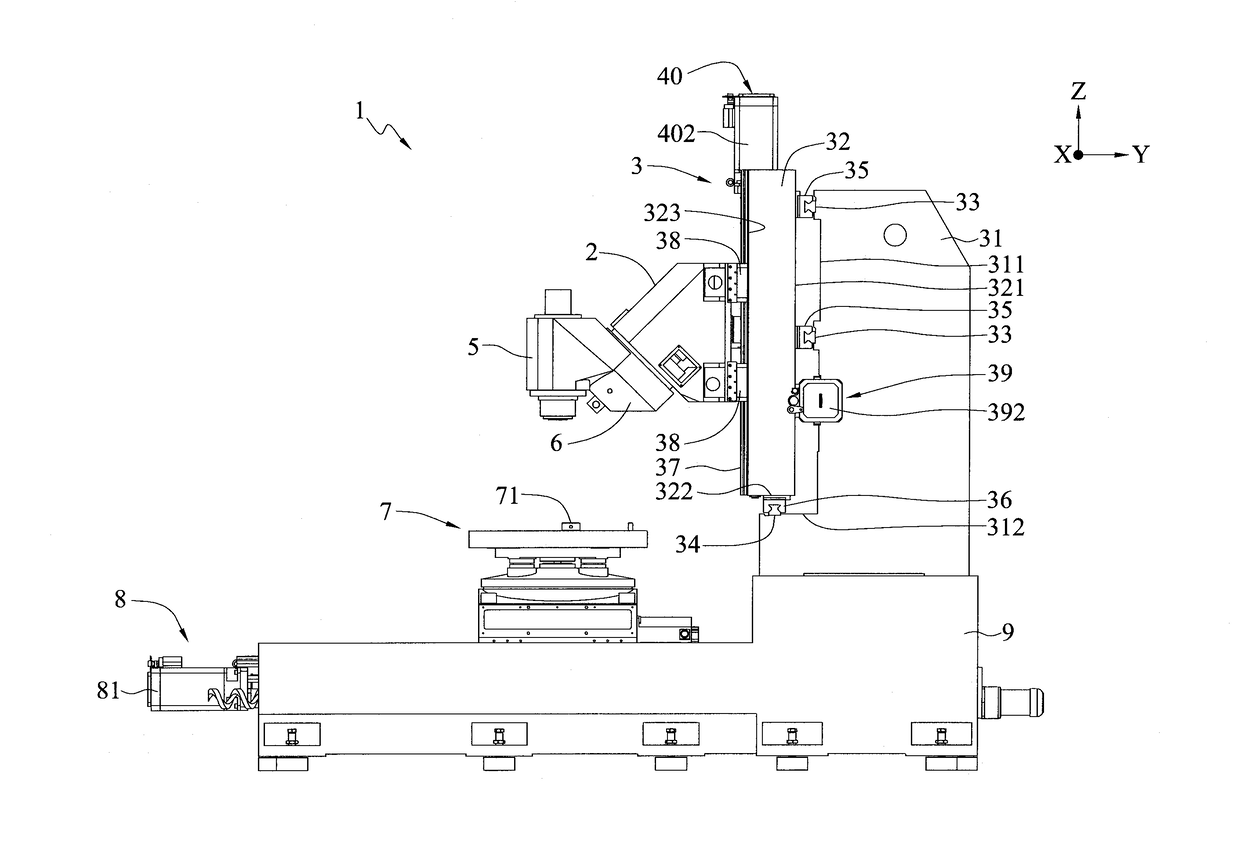
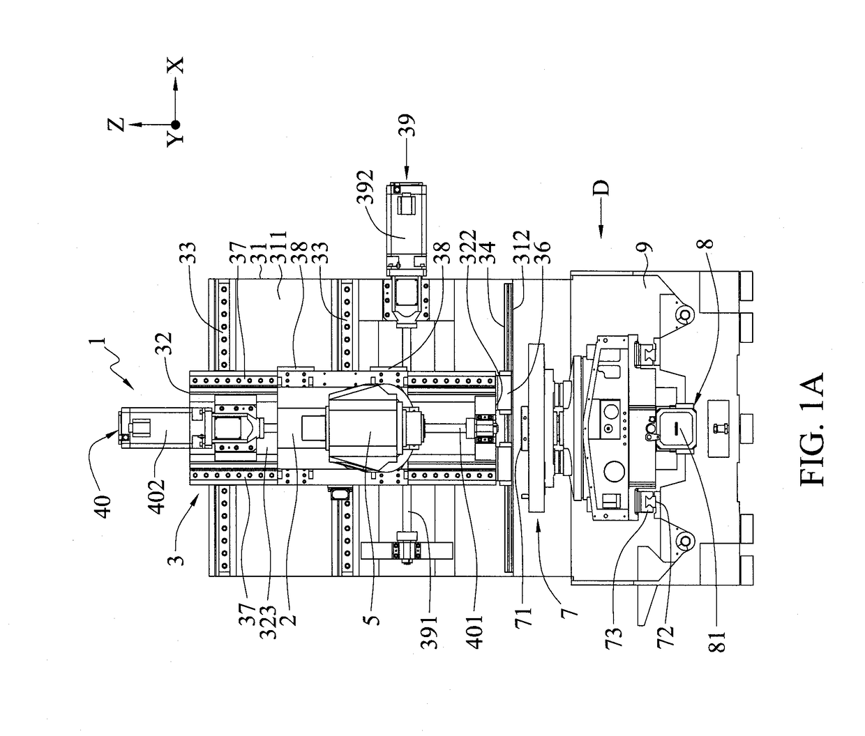
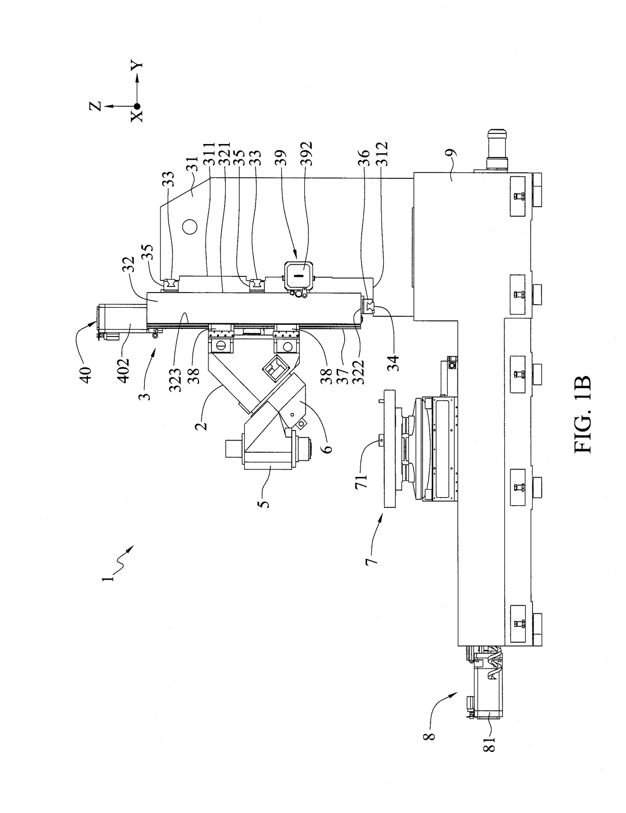
[0025]FIG. 1A is a schematic front view of a machine tool 1 and a feed saddle structure 3 of the machine tool 1 according to a first embodiment of the present disclosure. FIG. 1B is a schematic side view of the machine tool 1 and the feed saddle structure 3 of the machine tool 1 along a direction D. The machine tool 1 has a headstock 2 and a feed saddle structure 3 for carrying and moving components such as the headstock 2.

[0026]The feed saddle structure 3 has a fixed column 31, a feed saddle 32, two first guide rails 33, a second guide rail 34, two first sliders 35, and a second sl...


PUM

PropertyMeasurementUnit
Timeaaaaaaaaaa

Abstract

A machine tool and a feed saddle structure thereof are provided. The feed saddle structure includes: a fixed column having a first vertical side and a horizontal side adjacent to the first vertical side; a feed saddle having a second vertical side corresponding in position to the first vertical side of the fixed column, and a bottom portion being adjacent to the second vertical side and corresponding in position to the horizontal side of the fixed column; a first guide rail and a second guide rail disposed on the first vertical side and the horizontal side of the fixed column, respectively; and a first slider and a second slider disposed on the second vertical side and the bottom portion of the feed saddle, respectively, and engaged with the first guide rail and the second guide rail, respectively, thereby increasing the dynamic and static rigidity of the machine tool.

Description

BACKGROUND OF THE DISCLOSURE[0001]1. Technical Field[0002]The present disclosure relates to machine tools and feed saddle structures thereof, and, more particularly, to a machine tool and a feed saddle structure thereof having a plurality of guide rails.[0003]2. Description of Related Art[0004]In a conventional four-axis or five-axis machine tool (first type), a spindle head is disposed on a moving column for movement, and the moving column is supported and moved by two horizontal guide rails positioned under a bottom portion of the moving column.[0005]However, the moving column of the above-described first type machine tool is quite long, and the two horizontal guide rails are positioned far away from the spindle head, thus reducing the rigidity of the machine tool. Accordingly, a machine tool having a short moving column (second type) is developed to increase the rigidity of the machine tool and the bending strength of the spindle head.[0006]To improve the dynamic performance of t...

Claims


Application Information

Patent Timeline
IPC IPC(8): B23Q1/62B23Q1/01
CPCB23Q1/621B23Q1/015Y10T409/309576B23Q1/017Y10T409/307056
Inventor LIN, WEI-JUNLIAO, CHIEN-CHIHLIANG, SHUO-PENG
Owner IND TECH RES INST
Why Eureka
Try Eureka