A reel pipe motor and a rolling curtain positioning control system

Active Publication Date: 2017-06-29
NINGBO XIANFENG NEW MATERIAL
View PDF8 Cites 14 Cited by
  • Summary
  • Abstract
  • Description
  • Claims
  • Application Information

AI Technical Summary

Benefits of technology

The present invention provides a reel pipe motor with a conveniently turn-on or-off power supply. The outer surface of the tubular part is covered with a crown wheel and a clamp to prevent it from falling off. The motor is controlled by a bead switch, which makes it more convenient to use. The hollow rod prevents the bead chain or rope from winding onto the neck of children. The starting end sensing element and the terminating end sensing element on both ends of the curtain cloth, as well as the sense control configuration, ensure the curtain cloth is not affected by the winding looseness or tightness of the curtain cloth on the reel pipe, resulting in higher moving precision.

Problems solved by technology

It is an important issue to precisely wind up a rolling curtain by electric drive in the normal use of an electric rolling curtain.
However, as the rolling curtain is usually flexible, under impacts of circumstantial factors, the number of turns of the flexible rolling curtain of a certain length wound on the roller would vary in such a manner that the rolling curtain is inaccurately positioned, which affects the use and appearance of the rolling curtain.
Conventional reel pipe motors have to he turned on or off by turning on or off the general power supply, which makes for inconvenient. use.
Furthermore, the conventional electric rolling curtain usually has to be powered on by an external power supply, meaning the rolling curtain could not normally be rolled down lithe power is cut off.

Method used


Image

  • A reel pipe motor and a rolling curtain positioning control system
  • A reel pipe motor and a rolling curtain positioning control system
  • A reel pipe motor and a rolling curtain positioning control system

Examples


Embodiment Construction

[0038]Embodiments of the present invention will be described in detail below with reference to the drawings. However, the present invention shall not be limited to these embodiments.

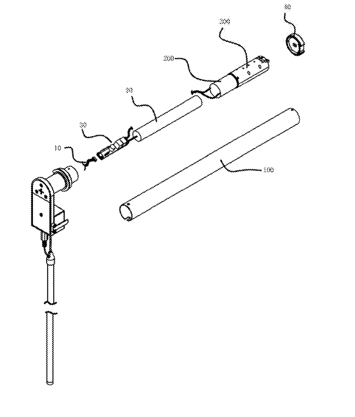
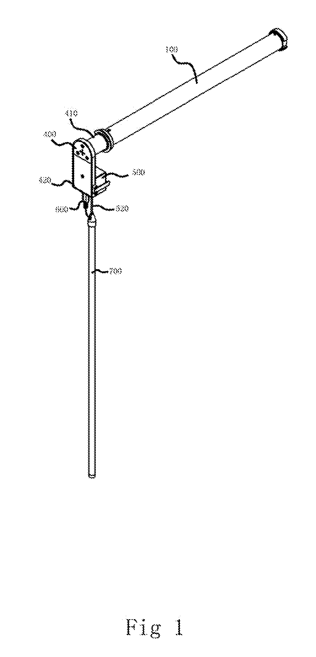
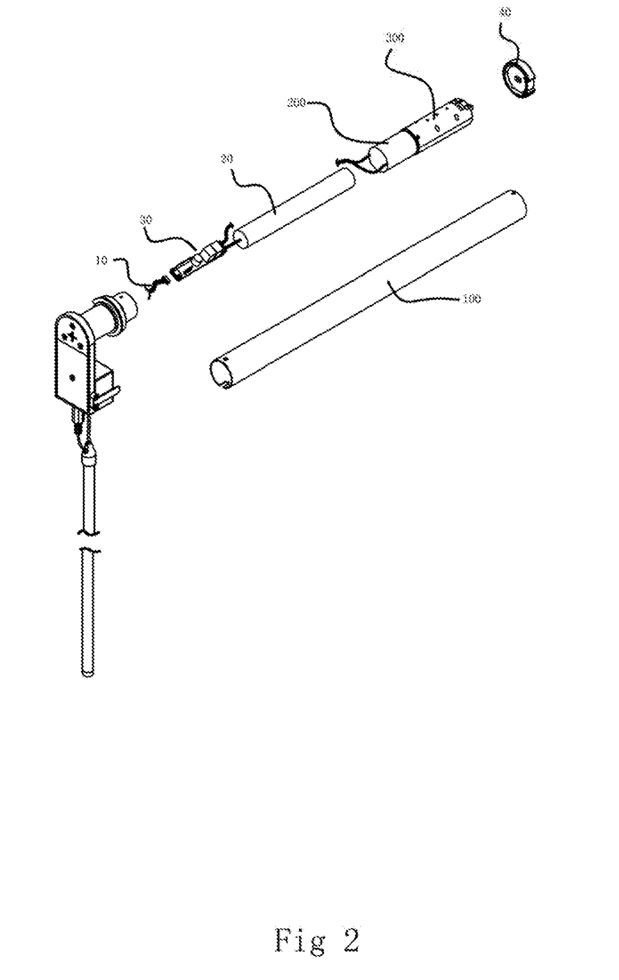
[0039]With reference to FIGS. 1 and 2, the reel pipe motor of the invention comprises a casing 100; a motor 200 and a speed reduction assembly 300 disposed within the casing 100 an L-shape motor end head 400 having a tubular part 410 and a box part 420 which could be connected with the casing; a switch box 500 disposed on the outer surface of the box part, in which a switch control panel 510 and a bead switch 520 are located; a power supply plug 600 and a hollow rod 700 The bead switch 520 is connected with the hollow rod 700. The bead switch 520 could be operated by pulling the hollow rod 700. The first end of the power supply plug 600 is electrically connected with the switch control panel 510 and the second end thereof extends into the hollow rod 700 and is electrically connected with an external powe...


PUM


Abstract

The present invention provides a reel pipe motor, comprising a casing; a motor and a speed reduction assembly disposed within the casing; an L-shape motor end head having a tubular part and a box part which could be connected with the casing, a switch box disposed on the outer surface of the box part, in which a switch control panel and a bead switch are located; and a power supply plug and a hollow rod. The bead switch is connected with the hollow rod. The bead switch could be operated by pulling the hollow rod. A first end of the power supply plug is electrically connected with the switch control panel, and a second end thereof extends into the hollow rod and is electrically connected with an external power supply. This invention further discloses a rolling curtain positioning control system comprising the said reel pipe motor.

Description

BACKGROUND OF THE INVENTION[0001]Field of Invention[0002]The present invention relates to the technical field of rolling curtain control, in particular, to a reel pipe motor and a roiling curtain positioning control system.[0003]Related Art[0004]The rolling curtain is usually manually driven or electrically driven in use. It is an important issue to precisely wind up a rolling curtain by electric drive in the normal use of an electric rolling curtain. In the conventional art, the upward and downward positioning of the rolling curtain is generally controlled by calculating the number of turns of the roller so that the electric rolling curtain can be precisely wound onto the reel pipe. The rolling curtain will move up or down for a fixed distance for each turn of the roller. The overall distance of upward or downward movement of the rolling curtain is equivalent to the number of turns of the roller multiplied by the upward or downward distance of the rolling curtain brought by each tu...

Claims


Application Information

Patent Timeline
IPC IPC(8): E06B9/72E06B9/42E06B9/50
CPCE06B9/72E06B2009/6845E06B9/42E06B9/50E06B9/40
Inventor LU, XIANFENGCHEN, JIANGUOHU, MENGXU
Owner NINGBO XIANFENG NEW MATERIAL
Why Eureka
Try Eureka