Ultrasonic device, ultrasonic probe, electronic equipment, and ultrasonic imaging apparatus
a technology of ultrasonic devices and ultrasonic probes, applied in measurement devices, mechanical vibration separation, instruments, etc., can solve problems such as difficulty in forming acoustic matching layers with desired thicknesses
- Summary
- Abstract
- Description
- Claims
- Application Information
AI Technical Summary
Benefits of technology
Problems solved by technology
Method used
Image
Examples
first embodiment
[0032]In this embodiment, an ultrasonic imaging apparatus for inspecting the inside of the human body is described as an example of electronic equipment.
[0033](1) Overall Configuration of Ultrasonic Imaging Apparatus
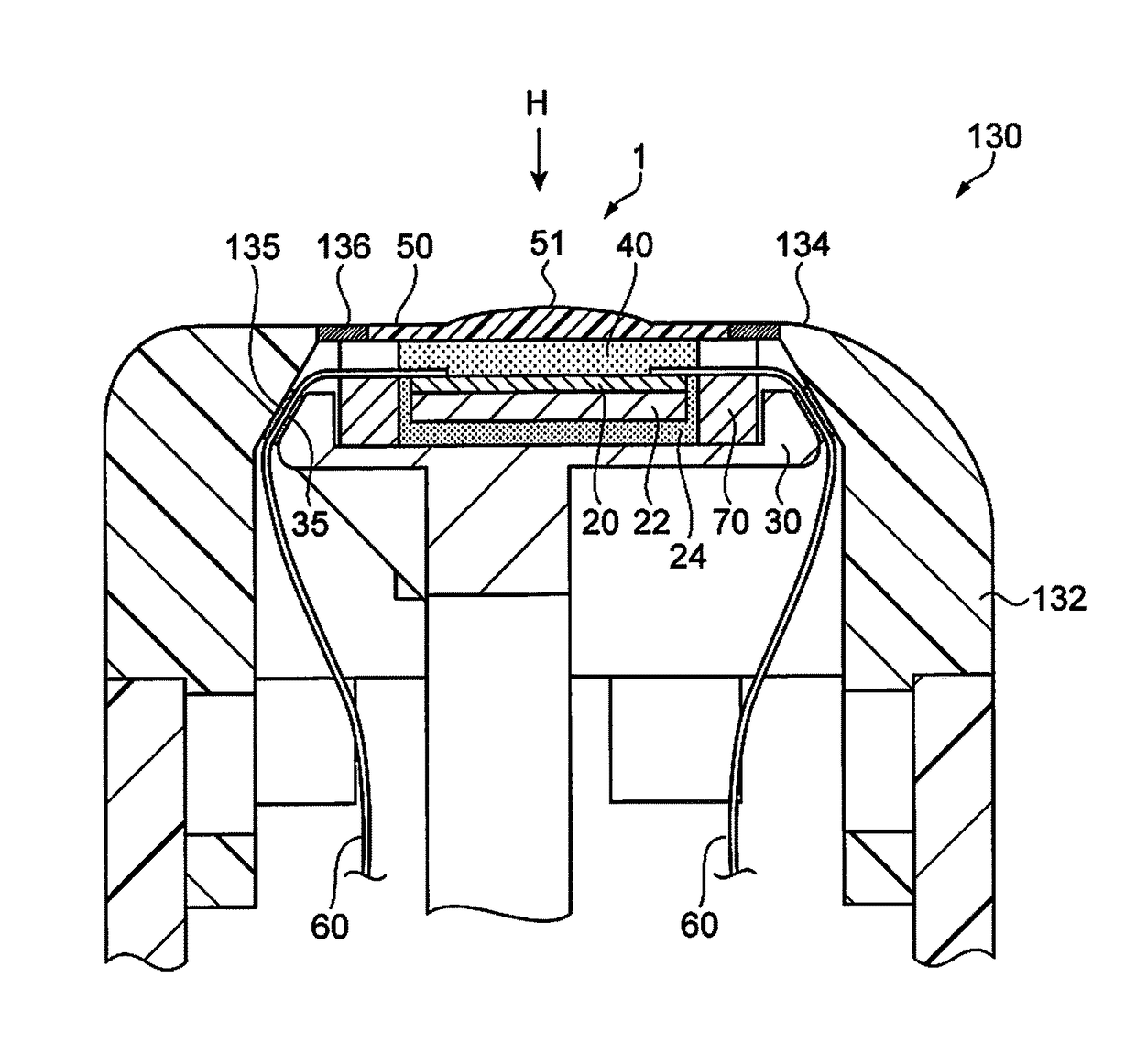
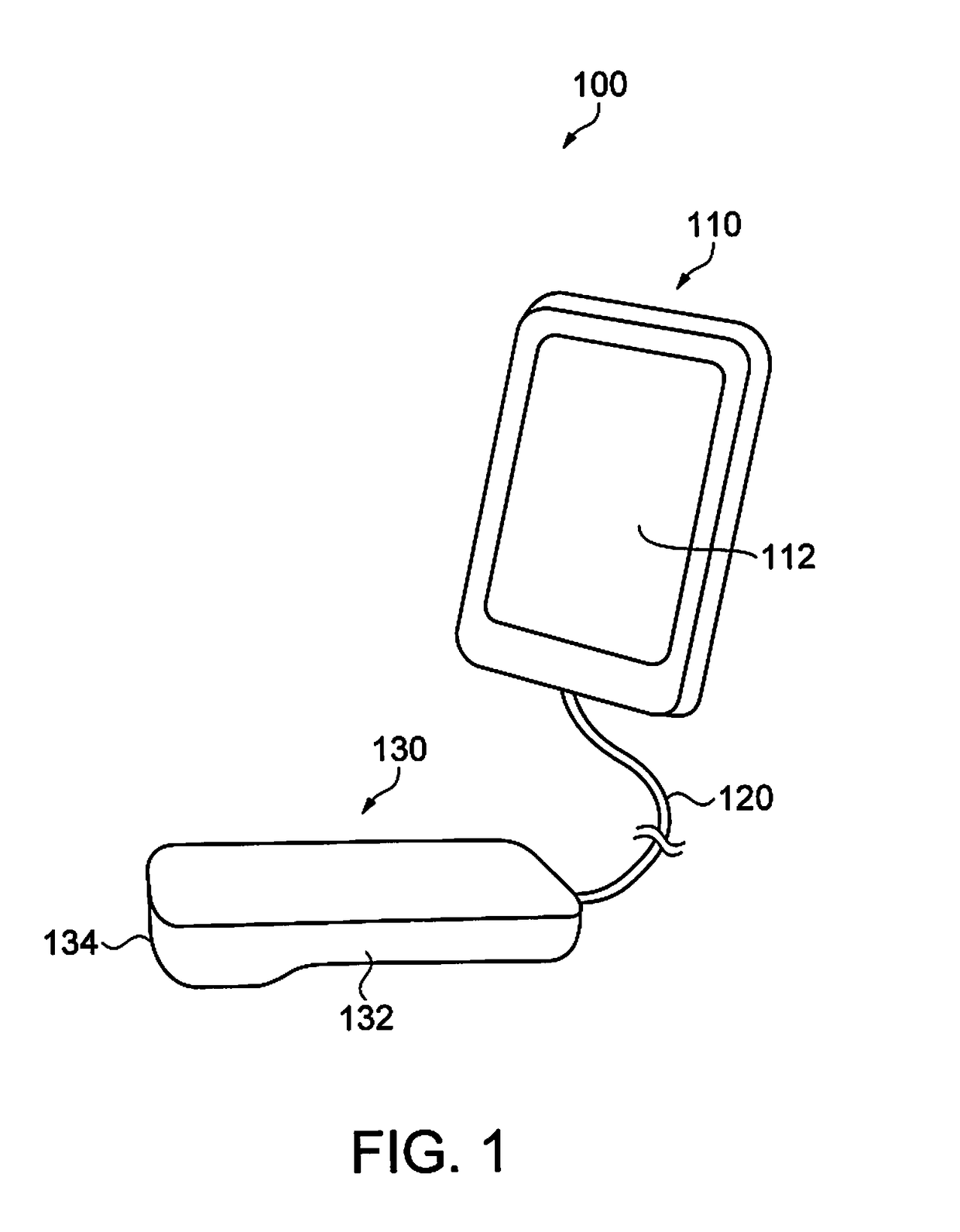
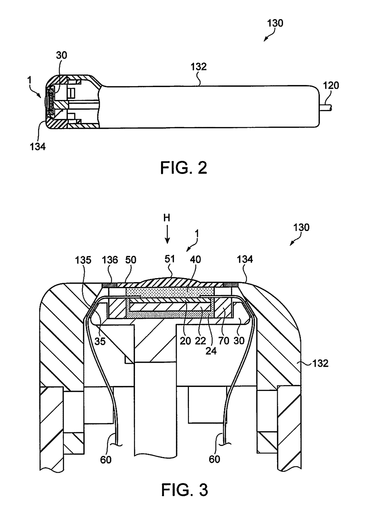
[0034]FIG. 1 shows a schematic outline of an ultrasonic imaging apparatus of this embodiment. FIG. 2 is a partial sectional view of an ultrasonic probe. FIG. 3 is an enlarged sectional view of a head portion of the ultrasonic probe.
[0035]As shown in FIG. 1, an ultrasonic imaging apparatus 100 includes an apparatus body 110 and an ultrasonic probe 130. The apparatus body 110 and the ultrasonic probe 130 are connected to each other by a cable 120. The apparatus body 110 and the ultrasonic probe 130 can exchange electrical signals via the cable 120.
[0036]The apparatus body 110 incorporates a display panel or the like as a display 112. In this embodiment, the display 112 is a touch panel display, and serves also as a user-interface unit (UI unit).
[0037]In the apparatus body ...
second embodiment
[0123]Next, an ultrasonic device of the second embodiment is described.
[0124]FIG. 16 is a sectional view showing a configuration of the ultrasonic device of this embodiment. FIG. 17 is a plan view showing a configuration of a fixing frame, as viewed from the back surface (surface in contact with the ultrasonic element array substrate).
[0125]This embodiment has the same configuration as the first embodiment, except that the fixing frame has a different structure from the first embodiment. Therefore, the same components as in the first embodiment are denoted by the same reference numerals, and the description thereof is omitted.
[0126]An ultrasonic device 4 shown in FIG. 16 is provided with a plurality of first projections 76 in portions, which come into contact with the acoustic lens 50, of the fixing frame 70a. The first projections 76 are provided on each of both sides in the longitudinal direction of the fixing frame 70a, as shown in FIG. 17. The first projections 76 are formed at ...
third embodiment
[0132]Next, an ultrasonic device of the third embodiment is described.
[0133]FIG. 18 is a sectional view showing a configuration of the ultrasonic device of this embodiment. FIG. 19 is a plan view showing a configuration of an acoustic lens.
[0134]This embodiment has the same configuration as the first embodiment, except that the acoustic lens and the fixing frame each have a different structure from the first embodiment. Therefore, the same components as in the first embodiment are denoted by the same reference numerals, and the description thereof is omitted.
[0135]An ultrasonic device 5 shown in FIG. 18 is provided with a plurality of second projections 52 (first and second projections of the acoustic lens) in portions of the acoustic lens 50a that come into contact with the fixing frame 70b. The second projections 52 are provided on each of both sides in the longitudinal direction of the acoustic lens 50a, as shown in FIG. 19.
[0136]The portions of the fixing frame 70b that come int...
PUM
 Abstract
Description
Claims
Application Information
 - R&D Engineer
- R&D Manager
- IP Professional
- Industry Leading Data Capabilities
- Powerful AI technology
- Patent DNA Extraction
Browse by: Latest US Patents, China's latest patents, Technical Efficacy Thesaurus, Application Domain, Technology Topic.
© 2024 PatSnap. All rights reserved.Legal|Privacy policy|Modern Slavery Act Transparency Statement|Sitemap


