
Manufacturing method for bent member and hot-bending apparatus for steel material

Active Publication Date: 2017-07-13
NIPPON STEEL CORP
View PDF6 Cites 2 Cited by
  • Summary
  • Abstract
  • Description
  • Claims
  • Application Information

AI Technical Summary

Benefits of technology

The patent text describes a way to prevent a certain type of damage to a steel material, which can be used in manufacturing processes for bent members and hot-bending apparatus. This can increase productivity and efficiency, resulting in cost savings.

Problems solved by technology

However, high-strengthening, a decrease in weight, and a decrease in size of the bent member are further required.
However, there are problems that a material which can be used for the tube hydro-forming method is limited, shape flexibility is not sufficient in bending using the tube hydro-forming method, or the like.

Method used


Image

  • Manufacturing method for bent member and hot-bending apparatus for steel material
  • Manufacturing method for bent member and hot-bending apparatus for steel material
  • Manufacturing method for bent member and hot-bending apparatus for steel material

Examples


aspect example 1-2

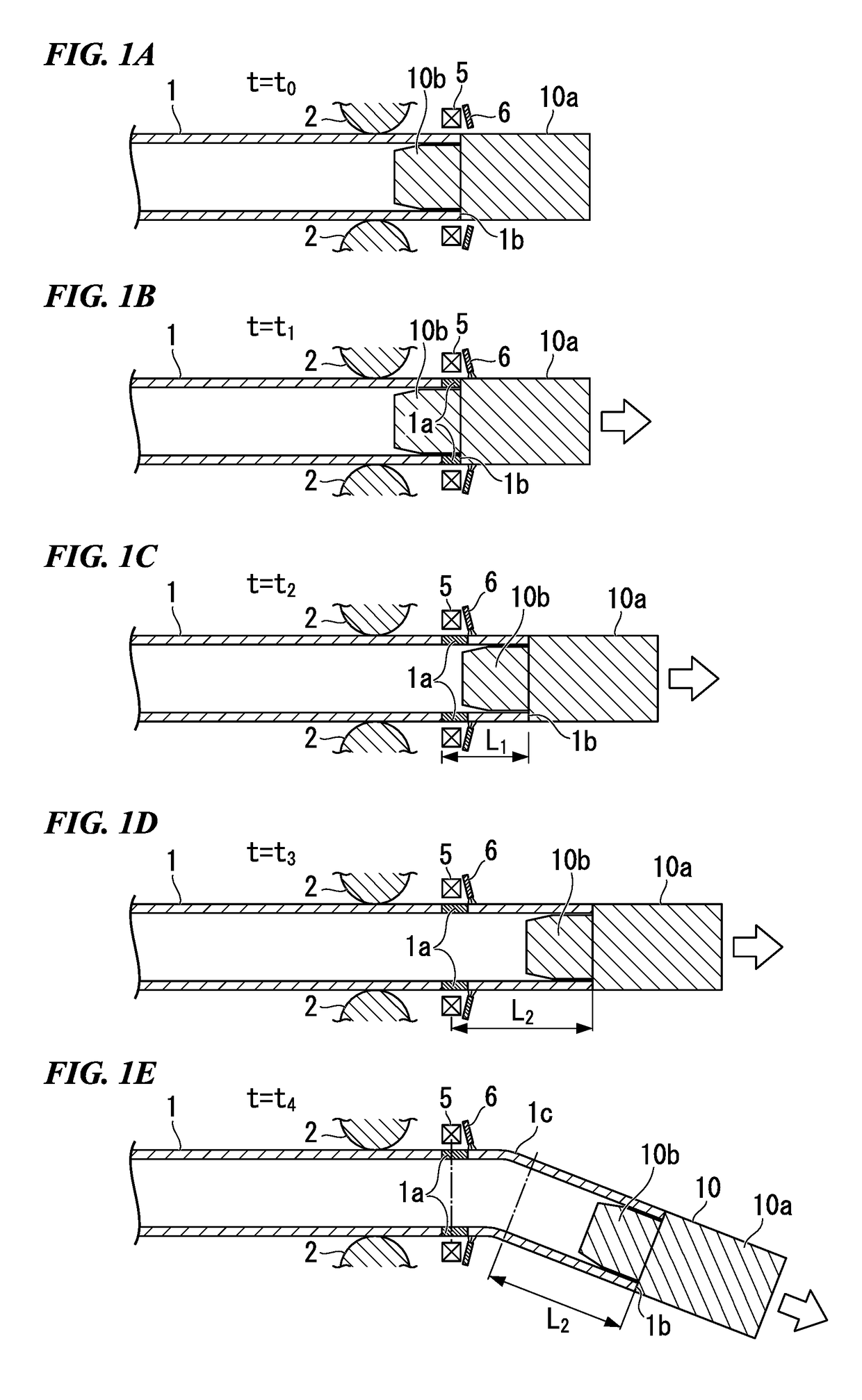
[0126]In Aspect Example 1-2, in order to cause the heating amount applied to the front end section 1b when the heated portion 1a is formed on the front end section 1b to be greater than the heating amount which is applied to the upstream side adjacent portion when the heated portion 1a is formed on the upstream side adjacent portion, the feeding speed of the steel pipe 1 is changed.

[0127]FIG. 5(a) is a graph which shows high-frequency electric energy (vertical axis) supplied to the induction heating device 5 of Aspect Example 1-2 with respect to time (horizontal axis). FIG. 5(b) is a graph which shows the feeding speed (vertical axis) of the steel pipe 1 in Aspect Example 1-2 with respect to time (horizontal axis).

[0128]In the aspect example 1-2, as shown in FIGS. 5(a) and 5(b), the induction heating of the steel pipe 1 performed by the induction heating device 5 and the feeding of the steel pipe 1 performed by the feeding device 3 are started simultaneously. As shown in FIG. 5(a), ...

aspect example 1-3

[0130]In Aspect Example 1-3, the heating amount applied to the front end section 1b of the steel pipe 1 when the heated portion 1a is formed on the front end section 1b is greater than the heating amount which is applied to the upstream side adjacent portion when the heated portion 1a is formed on the upstream side adjacent portion by changing high-frequency electric energy supplied to the induction heating device 5 while maintaining the feeding speed of the steel pipe 1 to be constant.

[0131]FIG. 6(a) is a graph which shows high-frequency electric energy (vertical axis) supplied to an induction heating device of Aspect Example 1-3 with respect to time (horizontal axis). FIG. 6(b) is a graph which shows a feeding speed (vertical axis) of the steel pipe in Aspect Example 1-3 with respect to time (horizontal axis).

[0132]In Aspect Example 1-3, as shown in FIGS. 6(a) and 6(b), the induction heating of the steel pipe 1 performed by the induction heating device 5 and the feeding of the ste...

second embodiment

[0139]In a manufacturing method for a bent member according to a second embodiment, by decreasing a non-quenching portion formed on the rear end section of the steel pipe as much as possible and heating a small-diameter portion of a chuck holding the rear end section of the steel pipe such that the heated temperature is not higher than 500° C. when a rear end section of a steel pipe is bent, productivity and economic efficiency in the manufacturing of the bent member are improved, and fatigue fracture of the small-diameter portion of the chuck holding the rear end section of the steel pipe is prevented.

[0140]FIGS. 22A to 22D are schematic views showing a state where the vicinity of a rear end section 1d of the steel pipe 1 is bent using the related art.

[0141]FIG. 22A shows a state at a time t4 when induction heating performed by the induction heating device 5 and the feeding of the steel pipe 1 performed by the feeding device 3 are performed. At the time t4, the rear end section 1d ...


PUM

PropertyMeasurementUnit
Temperatureaaaaaaaaaa
Speedaaaaaaaaaa

Abstract

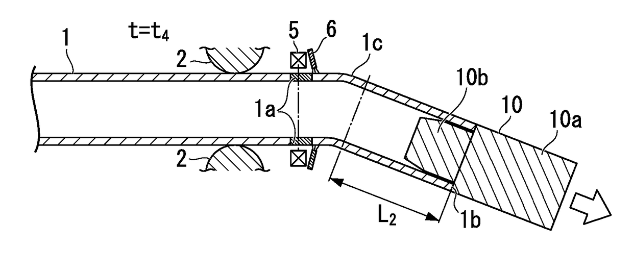
A manufacturing method for a bent member of the present invention includes a holding step of holding one end portion of a long steel material having an opening end in a longitudinal direction by a chuck, a feeding step of feeding the steel material in the longitudinal direction with the one end portion as a head after the holding step, a heating step of performing high-frequency induction heating on a portion of the steel material in the longitudinal direction to form a heated portion, a bending step of moving the chuck in a three-dimensional direction to apply a bending moment to the heated portion, and a cooling step of injecting a cooling medium to the heated portion to cool the heated portion after the bending step. When the heating step is started, the chuck is cooled by the cooling medium in a state where a heating amount applied to the one end portion when the heated portion is formed on the one end portion is greater than that of an upstream side adjacent portion adjacent to the upstream side of the one end portion as seen along a feeding direction of the steel material.

Description

TECHNICAL FIELD OF THE INVENTION[0001]The present invention relates to a manufacturing method for a bent member and a hot-bending apparatus for a steel material.[0002]Priority is claimed on Japanese Patent Application No. 2014-109361, filed on May 27, 2014, Japanese Patent Application No. 2014-209052, filed on Oct. 10, 2014, and Japanese Patent Application No. 2014-245639, filed on Dec. 4, 2014, the contents of which are incorporated herein by reference.RELATED ART[0003]A metal strength member, reinforced member, or structural member (hereinafter, referred to as a “bent member”) having a bent shape is used in automobile, various machines, or the like. A member having high strength, light weight, and a small size is required for the bent member. In the related art, for example, in order to manufacture the bent member, a method such as welding of a pressed product or punching and forging of a thick plate is used. However, high-strengthening, a decrease in weight, and a decrease in siz...

Claims


Application Information

Patent Timeline
IPC IPC(8): B21D9/04B21D7/16
CPCB21D7/16B21D9/04B21D7/12B21D7/08B21D7/162B21D37/16
Inventor OKADA, NOBUHIROKUBOTA, HIROAKITOMIZAWA, ATSUSHI
Owner NIPPON STEEL CORP
Learn More