Mounting Unit Comprising Drive Shaft and Drive Shaft Holder as Well as Motor Vehicle Comprising Mounting Unit

Active Publication Date: 2017-07-20
FORD GLOBAL TECH LLC
View PDF0 Cites 0 Cited by
  • Summary
  • Abstract
  • Description
  • Claims
  • Application Information

AI Technical Summary

Benefits of technology

[0017]In response to the front force which acts on the drive shaft, the drive shaft bracket rotates around the contact point between its contact portion and the selected supporting component, such that a pulling force is produced in the fastening portion which leads to a release of the fastening portion from the selected mounting component. The drive shaft bracket is thus not designed, as in the conventional manner, as a fixed connection that is not releasable and compressible in a typical collision. The drive shaft bracket is instead designed as a releasable component which is destroyed in a controlled manner in the event a large enough force is applied to the drive shaft. This

Problems solved by technology

When a specific axial force on a drive joint is exceeded, the outer hub breaks open such that a crack is produced in the outer hub.
This is often not desirable, however, for design reasons or due to other

Method used


Image

  • Mounting Unit Comprising Drive Shaft and Drive Shaft Holder as Well as Motor Vehicle Comprising Mounting Unit
  • Mounting Unit Comprising Drive Shaft and Drive Shaft Holder as Well as Motor Vehicle Comprising Mounting Unit
  • Mounting Unit Comprising Drive Shaft and Drive Shaft Holder as Well as Motor Vehicle Comprising Mounting Unit

Examples


Embodiment Construction

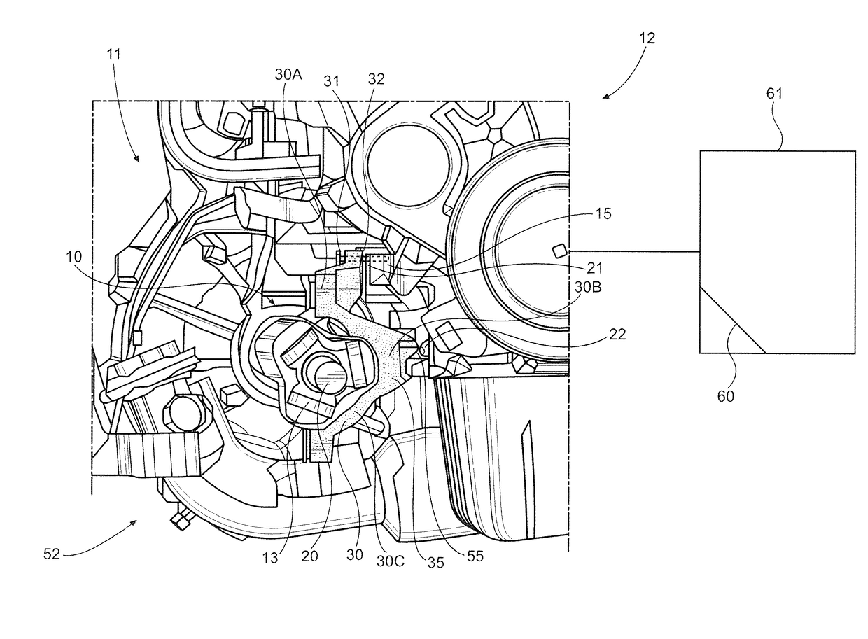
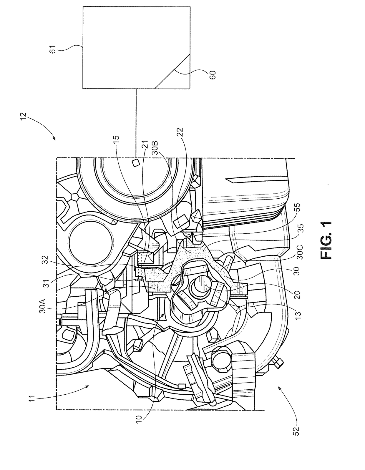
[0028]With initial reference to FIG. 1 there is shown an embodiment of a mounting unit 10 according to the invention in the installed state. The mounting unit 10 shown in FIG. 1 in a front region 11 of a front wheel driven motor vehicle 12 comprises an engine block 15, at least one drive shaft 20 with a tripod joint 13 for the transmission of force between the drive shaft 20 and an axle gear, not shown. The drive shaft 20 is preferably a front wheel drive shaft for driving the front wheels of the vehicle and the rear wheels may or may not be driven. The drive shaft 20 is fastened via a drive shaft holder 30, also referred to as a drive shaft bracket, to a mounting component 21, which is formed from part of the engine block 15, wherein in FIG. 1 only a right-hand half of the drive shaft bracket 30 is shown. The left-hand half is not shown, wherein both halves form an annular holder having an upper region 30a, a center region 30b and a lower region 30c. The half which is not shown is ...


PUM


Abstract

A mounting unit for a motor vehicle, comprising a drive shaft bracket fastening a drive shaft to a mounting component of the motor vehicle. The drive shaft bracket is fastened to the mounting component of the motor vehicle by a fastening portion. The drive shaft bracket, in the event of a front force on the drive shaft, is supported by a contact portion of the bracket via a contact point on a supporting component of the motor vehicle, which causes a rotation of the drive shaft bracket around the contact point. The rotation causes a joint between the fastening portion and the mounting component to be released.

Description

CROSS REFERENCE TO RELATED APPLICATIONS[0001]This application claims priority to German Patent Application Number 102016200741.6 filed on Jan. 20, 2016, the entire contents of which are incorporated herein by reference.BACKGROUND OF THE INVENTION[0002]The invention relates to a mounting unit for a drive shaft of a motor vehicle and a combination of a motor vehicle including the mounting unit. In this case, the mounting unit comprises a drive shaft holder, also referred to as a drive shaft bracket, for fastening at least one drive shaft to a mounting component, such as the engine block of the motor vehicle.[0003]In order to increase the occupant safety in passenger motor vehicles, in particular, in the case of frontal impacts, various measures are known in which components in a front region of a vehicle are collapsed when predefined impact forces are exceeded, so as to permit a controlled deformation of parts in the front region of the vehicle. Thus, the forces from the impact are no...

Claims


Application Information

Patent Timeline
IPC IPC(8): B60K17/24
CPCB60Y2410/102B60K17/24B60Y2306/01
Inventor MECKENSTOCK, DANIEL
Owner FORD GLOBAL TECH LLC
Why Eureka
Try Eureka