Ergonomic vehicle control system

a vehicle control and ergonomic technology, applied in the direction of hand levers, propulsion parts, motor deposition, etc., can solve the problems of large internal combustion power sources, accidents or close calls, and difficult for occupants to safely operate a vehicle, so as to improve the safety of occupants during the operating conditions

Inactive Publication Date: 2005-10-13
CRAWFORD FRANCIS JR
View PDF11 Cites 6 Cited by
  • Summary
  • Abstract
  • Description
  • Claims
  • Application Information

AI Technical Summary

Benefits of technology

[0016] The control system further includes a plurality of elongated roll bars having opposed end portions connected to selects portions of vehicle frame. Such plurality of roll bars preferably extend across a vehicle width for providing structural support thereto. Advantageously, the present invention further includes a mechanism for deploying a plurality of airbags mounted on the plurality of roll bars. Such a deploying mechanism causes the plurality of roll bar airbags to deploy down and forward to thereby improve occupant safety during operating conditions.

Problems solved by technology

Due to the coordination involved in operating numerous foot and hand pedals, it is easy for an operator to fail to timely or accurately engage such devices, resulting in accidents or close calls.
This is especially true for elderly or handicapped people who may suffer from reduced physical capabilities, making it difficult for them to safely operate a vehicle.
The use of these different systems requires a large internal combustion power source due to the loss of energy created by the transfer of energy from the power source to the transmission to the drive mechanism.
This decreases fuel economy, resulting in greater operating costs.

Method used


Image

  • Ergonomic vehicle control system
  • Ergonomic vehicle control system
  • Ergonomic vehicle control system

Examples


Embodiment Construction

[0023] The present invention will now be described more fully hereinafter with reference to the accompanying drawings, in which a preferred embodiment of the invention is shown. This invention may, however, be embodied in many different forms and should not be construed as limited to the embodiment set forth herein. Rather, this embodiment is provided so that this application will be thorough and complete, and will fully convey the true scope of the invention to those skilled in the art. Like numbers refer to like elements throughout the figures.

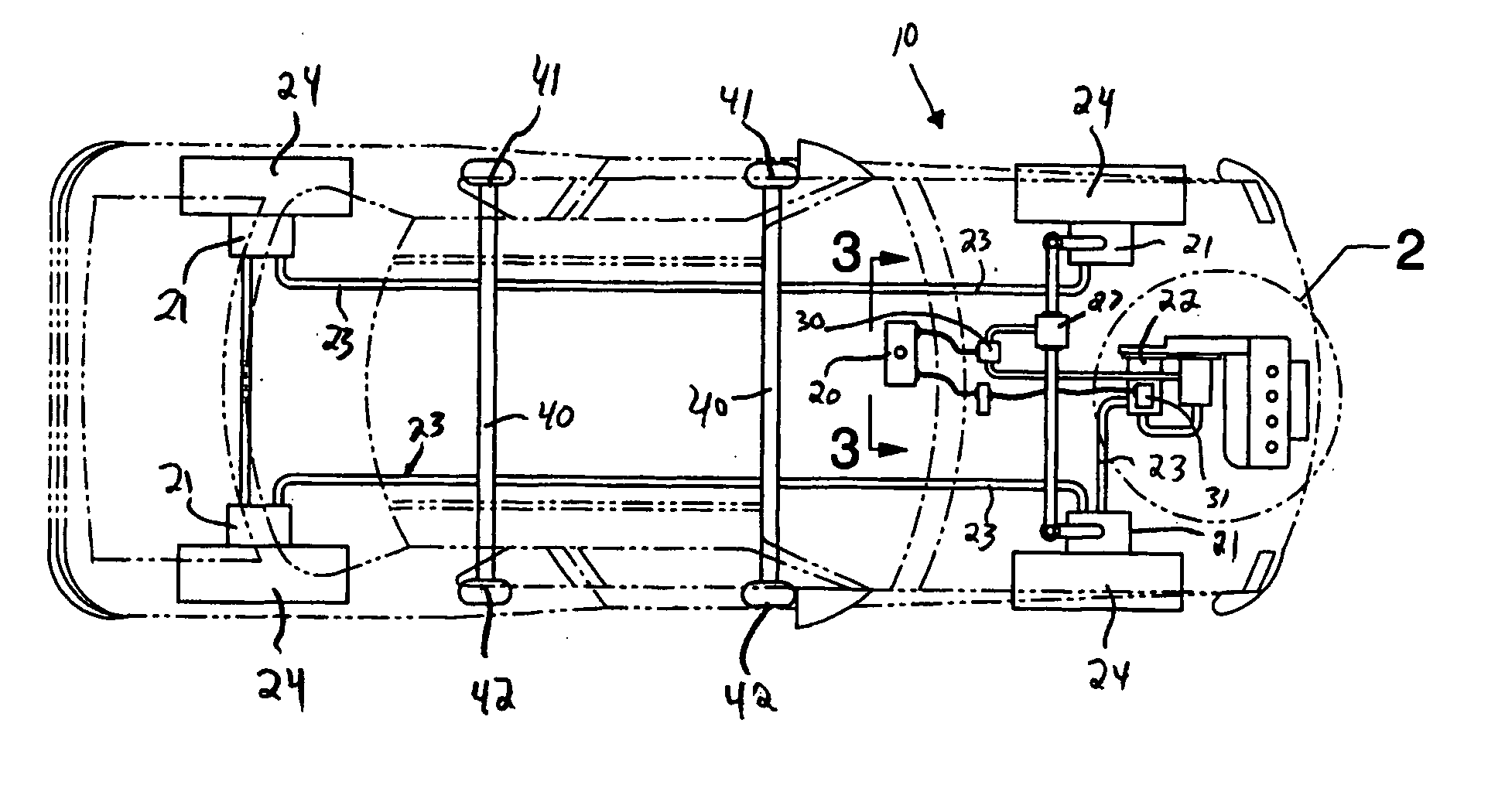
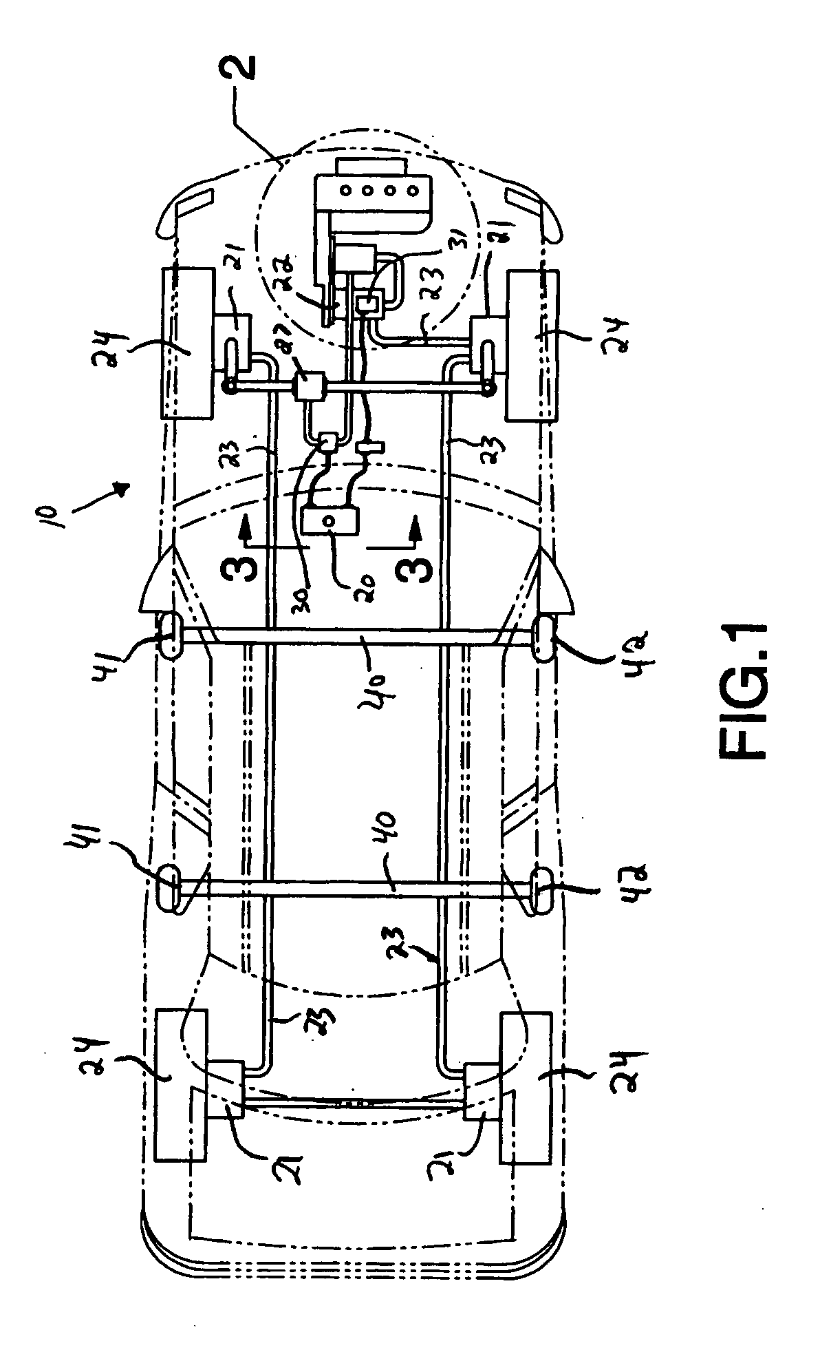
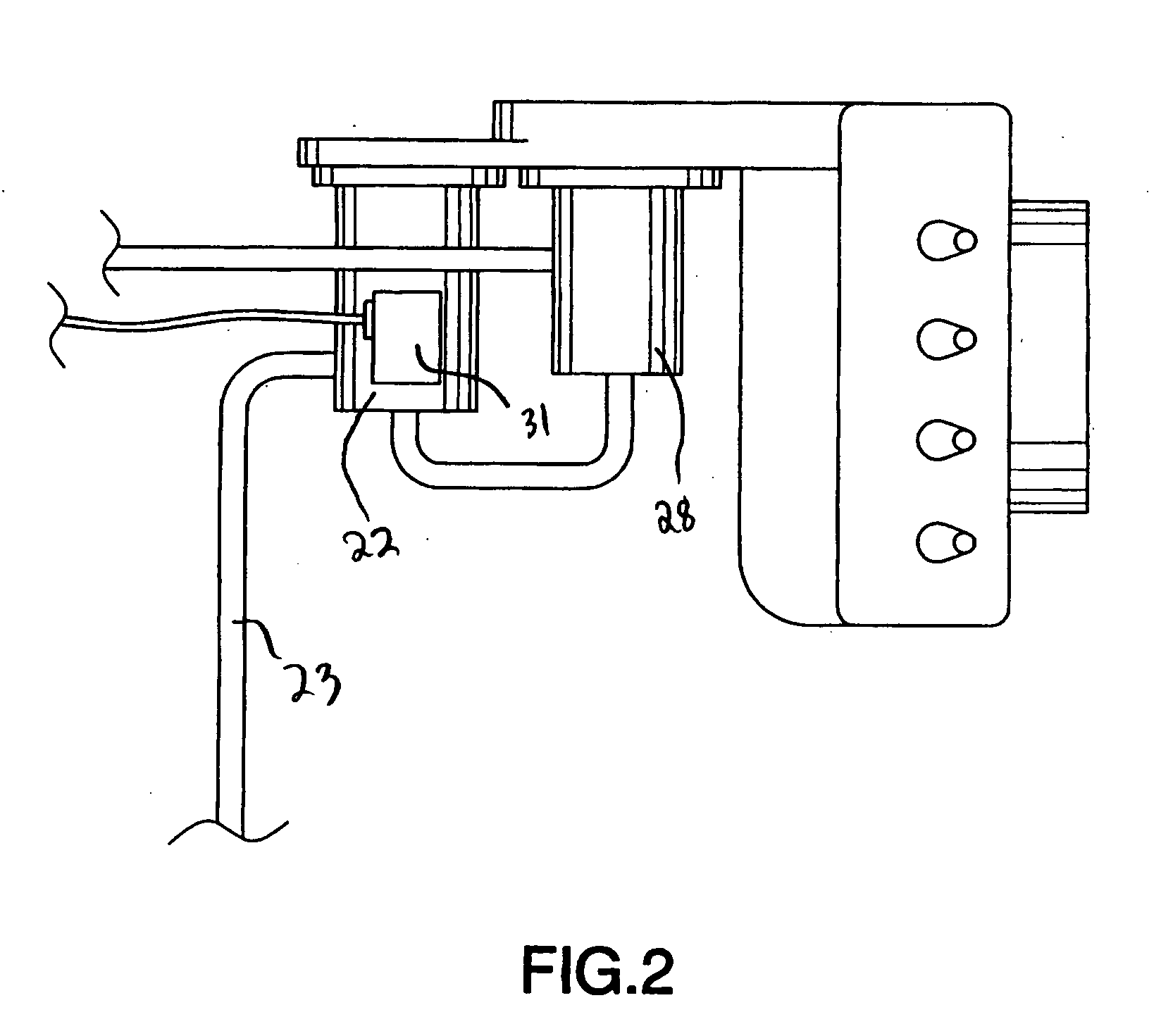
[0024] The apparatus of this invention is referred to generally in FIGS. 1-4 by the reference numeral 10 and is intended to provide an ergonomic vehicle control system for assisting drivers in operating a vehicle. It should be understood that the control system 10 may be used to operate many different types of vehicles and should not be limited to only automobiles.

[0025] Initially referring to FIG. 1, the control system 10 includes a contr...


PUM


Abstract

An ergonomic vehicle control system includes a control panel, a plurality of hydrostatic motors, a speed gear and a plurality of hydraulic lines for connecting the speed gear to the plurality of hydrostatic motors. The plurality of hydrostatic motors are operably connected to a plurality of vehicle wheels. The control system further includes a steering box and a hydrostatic pump operably connected thereto. A first controller is connected to the control panel, the steering box and the hydrostatic pump respectively. The control system further includes a second controller connected to the control panel and the speed gear respectively. The control panel further includes an elongated control lever electrically coupled to the first and second controllers so that an operator may effectively control movement of a vehicle. Such a control panel may be operably positioned on either side of a vehicle.

Description

CROSS REFERENCE TO RELATED APPLICATIONS [0001] Not Applicable. STATEMENT REGARDING FEDERALLY SPONSORED RESEARCH OR DEVELOPMENT [0002] Not Applicable. REFERENCE TO A MICROFICHE APPENDIX [0003] Not Applicable. BACKGROUND OF THE INVENTION [0004] 1. Technical Field [0005] This invention relates to vehicle control devices and, more particularly, to a vehicle control device for controlling multiple vehicular functions with one hand. [0006] 2. Prior Art [0007] The operation of a motor vehicle requires the coordination of a variety of motor and sensory skills. A driver must steer and operate dashboard functions such as turn signals, headlights, and wipers with his hands. The accelerator pedal and brake pedal are typically operated by one foot of a driver. In vehicles with manual transmissions, the driver's other foot is used to engage the clutch. [0008] Due to the coordination involved in operating numerous foot and hand pedals, it is easy for an operator to fail to timely or accurately eng...

Claims


Application Information

Patent Timeline
Patent Type & Authority Applications(United States)
IPC IPC(8): B60K7/00B62D1/12B62D1/02
CPCB62D1/02B62D1/12
Inventor CRAWFORD, FRANCIS JR.
Owner CRAWFORD FRANCIS JR
Why Eureka
Try Eureka