
An air bag and a method of folding an air bag

a technology of air bags and air bags, which is applied in the direction of vehicular safety arrangements, pedestrian/occupant safety arrangements, vehicular components, etc., can solve the problems of increased space requirements, increased air bag costs, and inability to carry, so as to reduce the force exerted on the head and/or neck, and improve the safety of occupants

Inactive Publication Date: 2006-06-22
FORD GLOBAL TECH LLC
View PDF29 Cites 5 Cited by
  • Summary
  • Abstract
  • Description
  • Claims
  • Application Information

AI Technical Summary

Benefits of technology

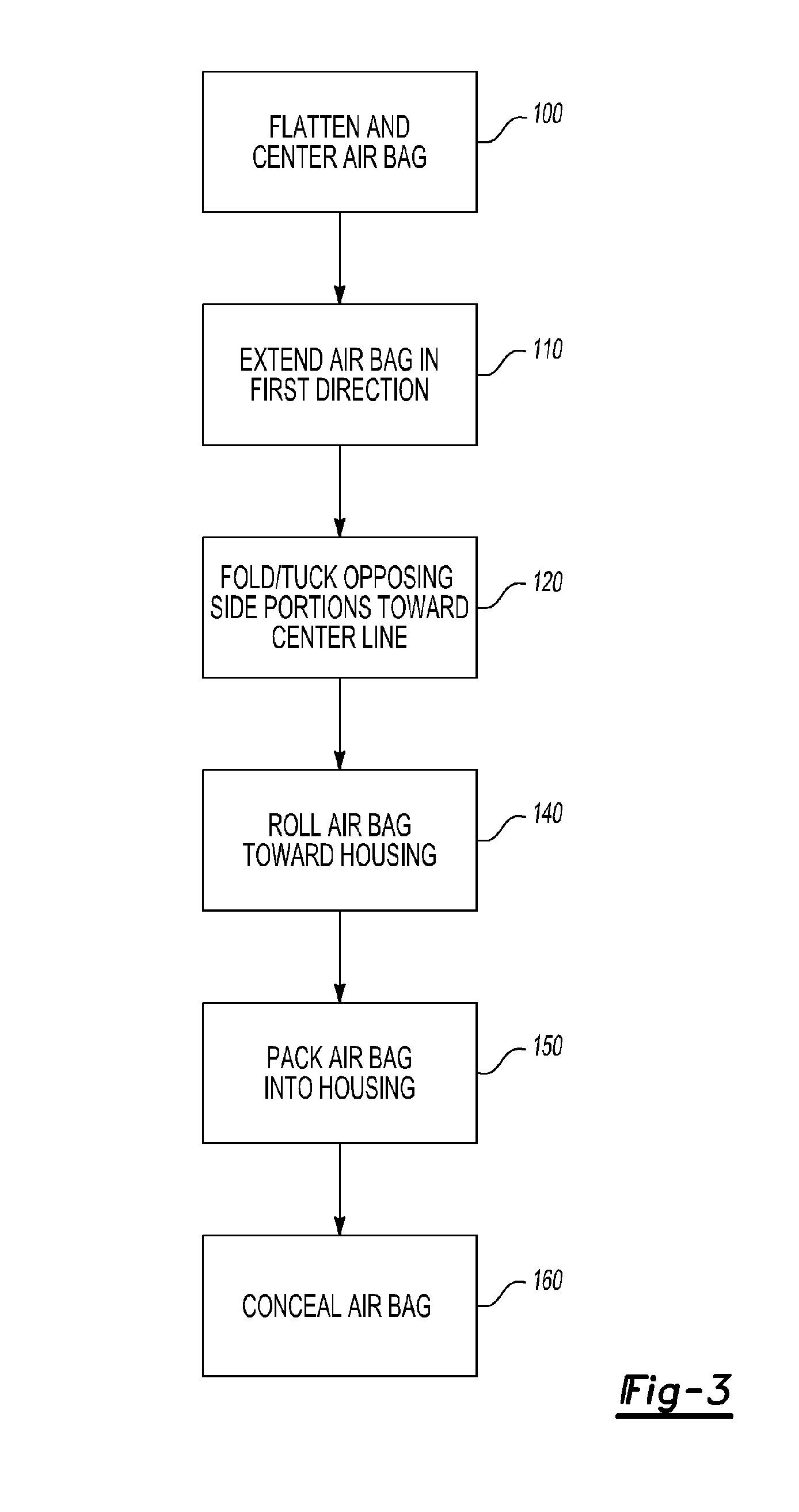
[0008] The method includes the steps of positioning the air bag such that a center line divides the front and back panels into symmetrical first and second side portions, extending the air bag in a first direction along the center line, positioning a first perimeter section of the first side portion toward the center line to create a first upper pleat and a first lower pleat, positioning a second perimeter section of the second side portion toward the center line to create a second upper pleat and a second lower pleat, and rolling the air bag in a second direction disposed opposite the first direction. The method controls the direction of air bag deployment to improve occupant protection without diffuser panels or increased packaging space.
[0018] The first and second side portions are disposed on opposite sides of a center line that symmetrically divides the front and back portions when the air bag is deflated and extended along the center line in a first direction. The first folded portion is formed along the first side portion and includes a first upper pleat, a first lower pleat, and a first fold disposed between the first upper and lower pleats. The second folded portion is formed along the second side portion and includes a second upper pleat, a second lower pleat, and a second fold disposed between the second upper and lower pleats. The rolled portion incorporates the first and second folded portions. The rolled portion may unroll away from a head of a vehicle occupant when the air bag is inflated to improve occupant safety and reduce forces exerted on the head and / or neck of the occupant.

Problems solved by technology

Such diffuser panels inadequately influenced the direction of air bag deployment and increased air bag costs.
Such “aimed” air bag modules increase space requirements and may be infeasible due to vehicle packaging constraints.
Even if there is sufficient packaging space, these air bag modules noticeably protrude from vehicle surfaces, thereby degrading passenger compartment aesthetics.
Moreover, such air bag modules may be aimed in a manner that reduces air bag effectiveness.
Consequently, the air bag may not prevent an occupant from contacting the steering wheel during an impact event.

Method used


Image

  • An air bag and a method of folding an air bag
  • An air bag and a method of folding an air bag
  • An air bag and a method of folding an air bag

Examples


Embodiment Construction

)

[0024] Certain terminology presented below is used for convenience in reference only and is not intended to be limiting. More specifically, directional language such as “front”, “back”, “top”, “bottom”, “upper”, “lower” and words of similar import designate directions shown in the drawings. Such directional terminology is used for clarity and is not intended to limit the orientation of any aspect of the invention to a particular plane or direction unless otherwise stated.

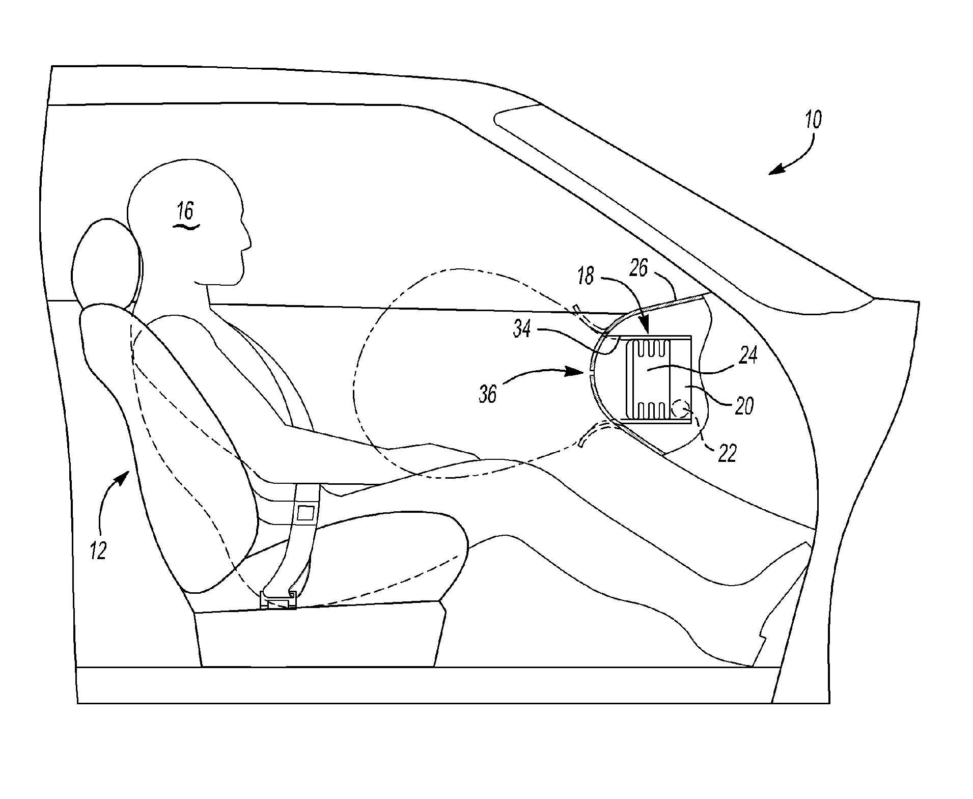
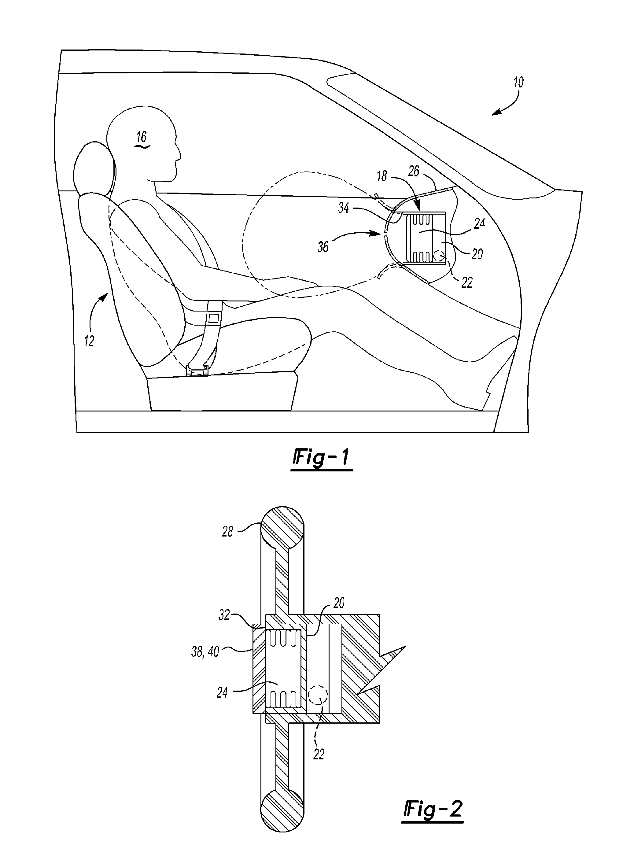
[0025] Referring to FIG. 1, a side view of a vehicle 10 is shown. The vehicle 10 includes a seat assembly 12 and an air bag module 14. The seat assembly 12 is adapted to receive an occupant 16. The air bag module 14 is adapted to deploy an air bag to cushion the occupant 16 during a vehicle impact event.

[0026] Referring to FIGS. 1 and 2, the air bag module 14 is shown in more detail. The air bag module 14 includes a housing 20, an inflator 22, and an air bag 24. The air bag module 14 may be disposed in any suitab...


PUM


Abstract

An air bag for a motor vehicle and a method of folding an air bag. The method includes the steps of positioning the air bag, extending the air bag in a first direction, positioning first and second perimeter sections of the air bag toward a center line to create upper and lower pleats, and rolling the air bag in a second direction disposed opposite the first direction.

Description

BACKGROUND OF THE INVENTION [0001] 1. Field of the Invention [0002] The present invention relates to an air bag and a method of folding an air bag, and more particularly to a method of folding an air bag to influence the direction of air bag deployment. [0003] 2. Background Art [0004] Motor vehicles may include one or more air bags that are inflated to cushion an occupant during a vehicle impact event. Previously, various designs were employed to bias the direction in which an air bag inflates during deployment. In one design, a motor vehicle air bag was equipped with an internal diffuser panel that directed inflation gas in a predetermined direction to inflate one side of an air bag before other portions of the air bag. Such diffuser panels inadequately influenced the direction of air bag deployment and increased air bag costs. [0005] In another design, an air bag module was aimed to direct air bag deployment. More specifically, the air bag module incorporated a housing in which an...

Claims


Application Information

Patent Timeline
Patent Type & Authority Applications(United States)
IPC IPC(8): B60R21/237B60R21/203
CPCB60R21/237B60R2021/23382
Inventor GUHA-THAKURTA, SARBASUBHA
Owner FORD GLOBAL TECH LLC
Learn More