Pedal support structure for vehicle

a technology for supporting structures and vehicles, applied in mechanical control devices, instruments, tractors, etc., can solve the problems of insufficient safety for passengers, difficult to perform tuning of the supporting structure, and large load applied to the foot placed on the pedal pad, so as to increase the safety of the occupant (driver) and effectively prevent the

Active Publication Date: 2008-07-15
CHIYODA IND +1
View PDF14 Cites 7 Cited by
  • Summary
  • Abstract
  • Description
  • Claims
  • Application Information

AI Technical Summary

Benefits of technology

[0015]It is therefore a first object of the present invention to provide a pedal support structure for use in a vehicle which increases safety of an occupant (driver) when an impact is applied to the front of a vehicle by effectively preventing a pedal from moving in a direction toward a passenger compartment by a stable rearward movement of a pedal bracket main body.

Problems solved by technology

In that event, there is such a possibility that a large load is applied to a foot placed on the pedal pad.
Hence, it is difficult to perform tuning of the support structure under estimating possible movement of relevant members, and there is such a possibility that safety for a passenger is not sufficiently attained.
When the accurate assembly cannot be obtained, the detaching behavior of the pedal bracket 112 from the bulkhead 102 becomes unstable.
Since the pedal bracket 112 has to be mounted on a vehicle within a limited space in a passenger compartment of a vehicle, the mounting accuracy cannot always be attained.

Method used


Image

  • Pedal support structure for vehicle
  • Pedal support structure for vehicle
  • Pedal support structure for vehicle

Examples


Embodiment Construction

[0053]Other features of this invention will be understood from the following description of exemplary embodiments, which are given for illustration of the present invention and are not intended to be limiting thereof.

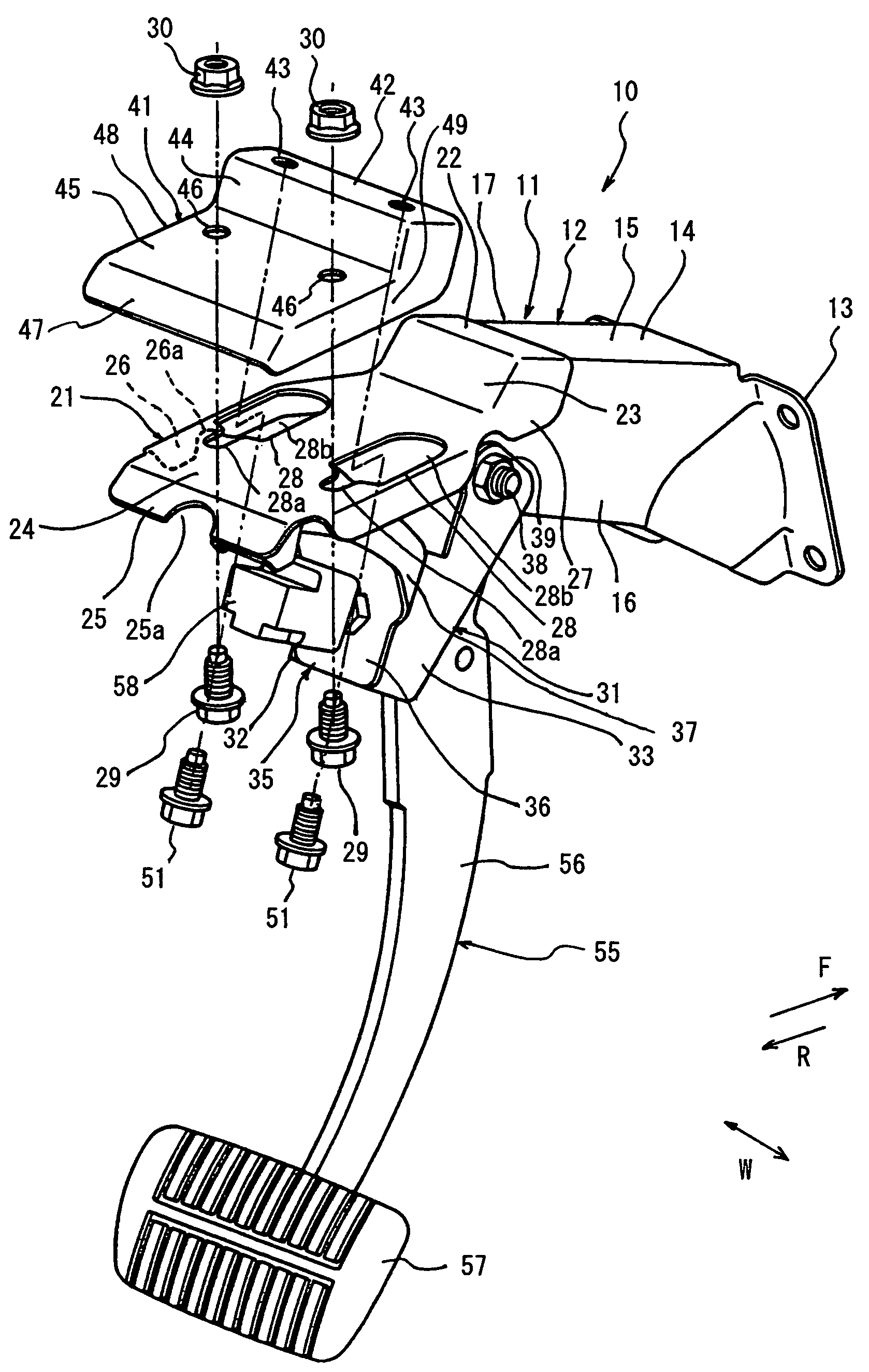
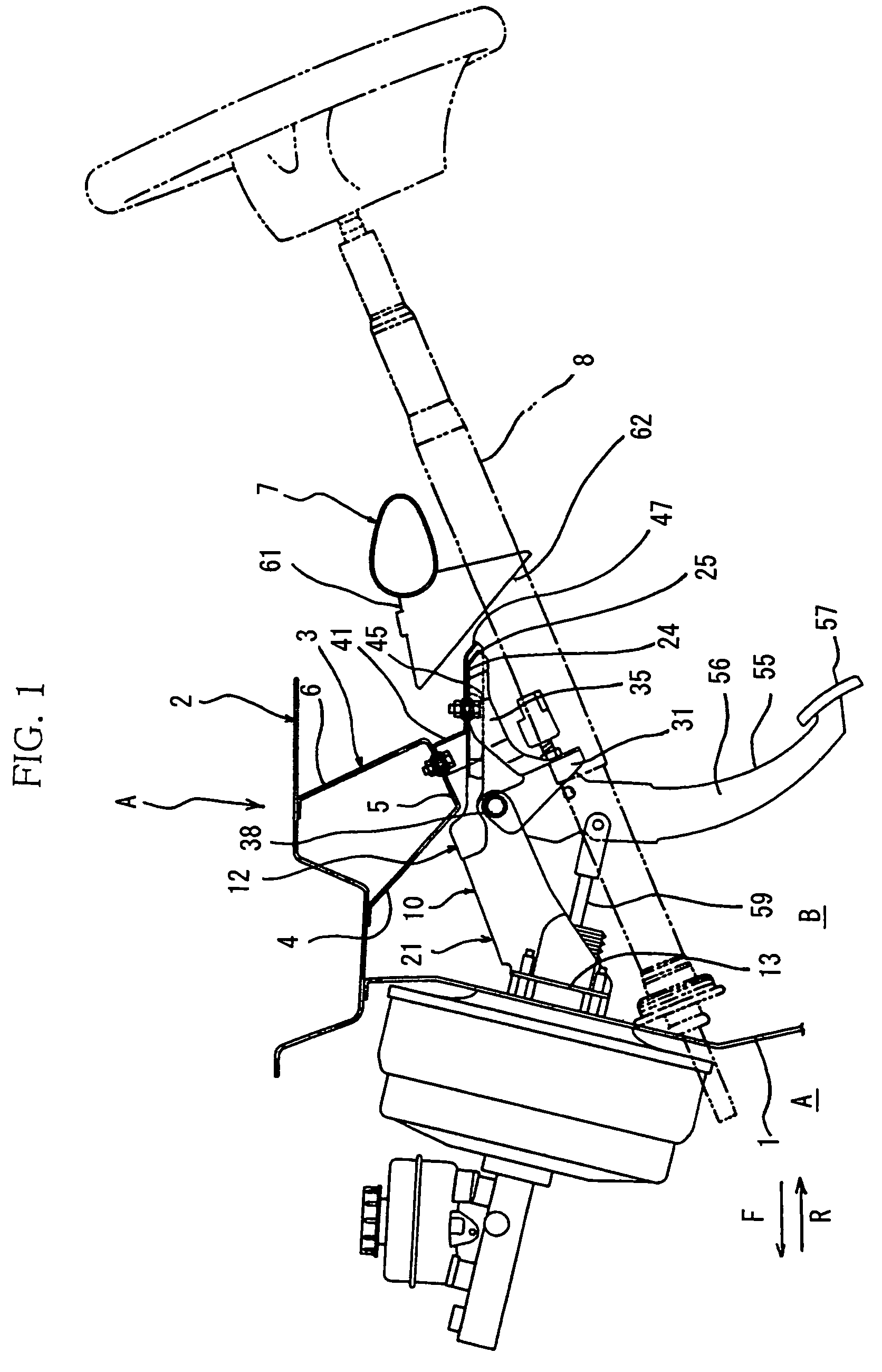
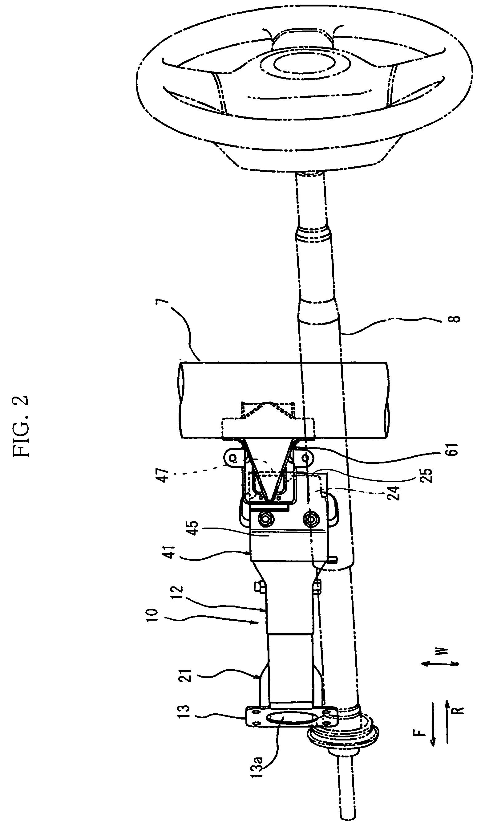
[0054]A pedal support structure for a vehicle of the present invention will be explained by referring to FIGS. 1 to 7 wherein a brake pedal for a vehicle is used as an example. FIG. 1 is a schematic side view for explaining a support structure for a brake pedal unit and related parts thereof. FIG. 2 is a plane view of a part of the pedal support structure shown in FIG. 1. FIG. 3 is an enlarged view of a part of the pedal support structure shown in FIG. 1. FIG. 4 is an exploded perspective view of a pedal support structure of the present invention. FIGS. 5 to 7 are side views of a pedal support structure of the present invention for explaining the function thereof. In the figures, arrows F, R and W indicate a front direction, a rear direction and a width direction of a v...


PUM


Abstract

A pedal support structure for a vehicle includes a main body provided between a catcher and a toe board. A front end of the main body is connected to the toe board, and a rear end thereof is spaced apart from a downwardly inclined surface of the catcher. A pedal bracket support part has a supporting surface supported on a bulkhead. The pedal bracket has a connecting surface, and the connecting surface is connected to the supporting surface. When a force is applied to a front part of the vehicle, the load rearwardly moves the main body, the connecting surface slides on the supporting surface, and the rear end of the main body slides downwardly along the inclined surface of the catcher. Accordingly, a pedal on the pedal support structure is moved toward an engine compartment of the vehicle without moving toward a passenger.

Description

BACKGROUND OF THE INVENTION[0001]1. Field of the Invention[0002]The present invention relates to a pedal support structure for a vehicle, and particularly to a pedal support structure for supporting a brake or clutch pedal.[0003]2. Discussion of the Related Art[0004]A brake pedal for a vehicle is provided in front of a seat for a driver in a passenger compartment. The brake pedal has a pedal pad and a pedal lever, and is actuated by a driver. The pedal pad is used as a step-on (treadle) surface which the driver stamps. The pedal lever extends approximately in a vertical direction and has the pedal pad at a bottom end thereof. A top end of the pedal lever is supported on a pedal bracket so as to pivot thereon and the pedal bracket is fixed to a toe board. The toe board is a partition interposed between an engine compartment and the passenger compartment. In front of the toe board, i.e., on an engine compartment side with respect to the toe board, a master cylinder is provided for amp...

Claims


Application Information

Patent Timeline
Patent Type & Authority Patents(United States)
IPC IPC(8): B60K28/10B60K23/02B62D25/08B60R21/02B60R21/09B60T7/06G05G1/30
CPCB60R21/09B60T7/065G05G1/32Y10T74/20888Y10T74/20534Y10T74/20528
Inventor HARASHIMA, HITOSHIOONO, TAKAMUNEYAMAGUCHI, OSAMU
Owner CHIYODA IND
Why Eureka
Try Eureka