

Clasp, watch band, and watch
- Summary
- Abstract
- Description
- Claims
- Application Information
AI Technical Summary
Benefits of technology
Problems solved by technology
Method used
Image

Examples
embodiment
Effect of Embodiment
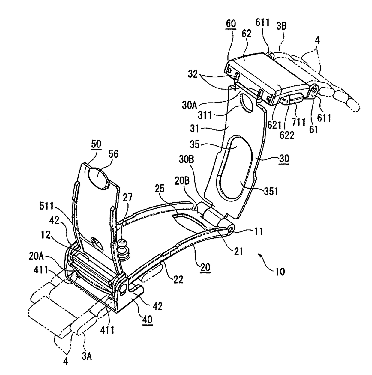
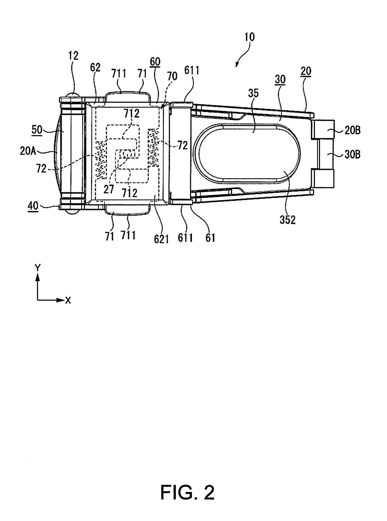
[0088]According to the embodiment described above, a mechanism in which the clasp 10 is attached to the first band 3A in a positionally adjustable manner can be configured to include the lower holding member 20, the lifting member 40, and the lock member 50. Moreover, a mechanism for locking / unlocking the clasp 10 can be configured to include the lock mechanism 70 provided in the main cover 60, and the lock pin 27 of the lower holding member 20. Therefore, it is not necessary to collectively provide the mechanisms in one main body portion. Thus, the structure of the clasp 10 can be simplified, the number of components can be reduced, and the clasp 10 can be reduced in weight.
[0089]Positional adjustment of the clasp 10 with respect to the first band 3A can be performed through an operation in which the lock member 50 is pivoted. The operation of positional adjustment is independent from an operation of opening / closing the clasp 10, in which the upper holding membe...
PUM
 Abstract
Description
Claims
Application Information