Container Having Generally L-Shaped Slotted Tracks To Facilitate Movement of Dunnage

a technology of slotted tracks and containers, which is applied in the direction of transportation and packaging, packaging foodstuffs, and packaged goods. it can solve the problems of unsatisfactory access, difficult and time-consuming removal of parts in containers, and undesirable delay in accessing and removing parts from containers. , to achieve the effect of efficient and safe removal, without unnecessary stress or strain on the operator

Active Publication Date: 2017-08-03
BRADFORD CO
View PDF0 Cites 1 Cited by
  • Summary
  • Abstract
  • Description
  • Claims
  • Application Information

AI Technical Summary

Benefits of technology

The invention is a container for unloading and loading parts from dunnage. The container has a movable door on one side, which can be lowered for ergonomic reasons. The front of the container can be accessed for easier loading and unloading without having to reach the back of the container. The container allows for efficient and safe removal or insertion of parts without unnecessary stress or strain on the operator. The container's design reduces the number of injuries, down time, and costs. The drop down door and L-shaped or U-shaped tracks inside the container make the unloading and loading process easier and less stressful on the operator's body.

Problems solved by technology

Some existing containers are difficult to access, which makes removal of the parts therein difficult and time consuming.
Any delay in access and removal of the part from the container is undesirable.
The size and / or weight of the parts or work pieces may cause stress or strain on the line worker and, more particularly, on the back of the worker when inserting or removing parts from such a container.
Such ergonomically unfriendly movements may cause physical trauma, pain and other injuries that may lead to lost production time.
This requires space around the container which may not be available, depending on the physical layout of the plant or facility.
The length (front to back) of certain containers may be limited because the container manufacturer needs to eliminate the need for a line worker to walk around the container to remove product from inside the container.
The more containers needed to ship a predetermined number of parts, the greater the cost to the shipper.
This movement by the line worker is ergonomically unfriendly because the line worker must lean forward and bend down and lift a part or workpiece up and over a wall into the container to remove the part or work piece from inside the container.
Similarly, when a part or workpiece must be inserted into a container, the line worker may have to lean forward and insert the part, which may be heavy, into its proper location inside the container, again experiencing ergonomically unfriendly movements.
Depending upon the number of times the line worker repeats this unnatural motion into the interior of the container, strain in the back, legs and arms may result.
The size and / or weight of the parts or work pieces may increase the strain on the line worker.
Thus, simply removing multiple parts during a work day may cause physical trauma, pain and other injuries that may lead to lost production time.

Method used


Image

  • Container Having Generally L-Shaped Slotted Tracks To Facilitate Movement of Dunnage
  • Container Having Generally L-Shaped Slotted Tracks To Facilitate Movement of Dunnage
  • Container Having Generally L-Shaped Slotted Tracks To Facilitate Movement of Dunnage

Examples


Embodiment Construction

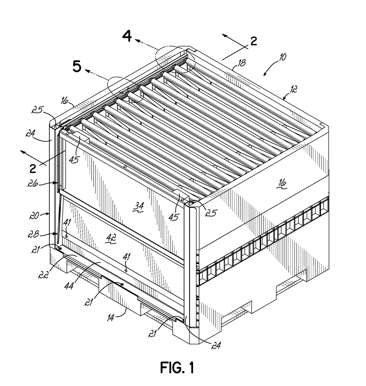
[0092]Referring to FIG. 1, there is illustrated a reusable and returnable container 10, according to one embodiment. The reusable and returnable container 10, as shown, comprises a body 12 having a base 14, opposed side walls 16 and a rear wall 18, all extending upwardly from the base 14. The side walls 16 and / or rear wall 18 may be hingedly secured to the base 14. A generally U-shaped front frame 20 may be fixedly secured to the side walls 16 and does not move relative to the side walls 16 after the container is assembled. The front frame 20 may be made of metal or any other suitable material.

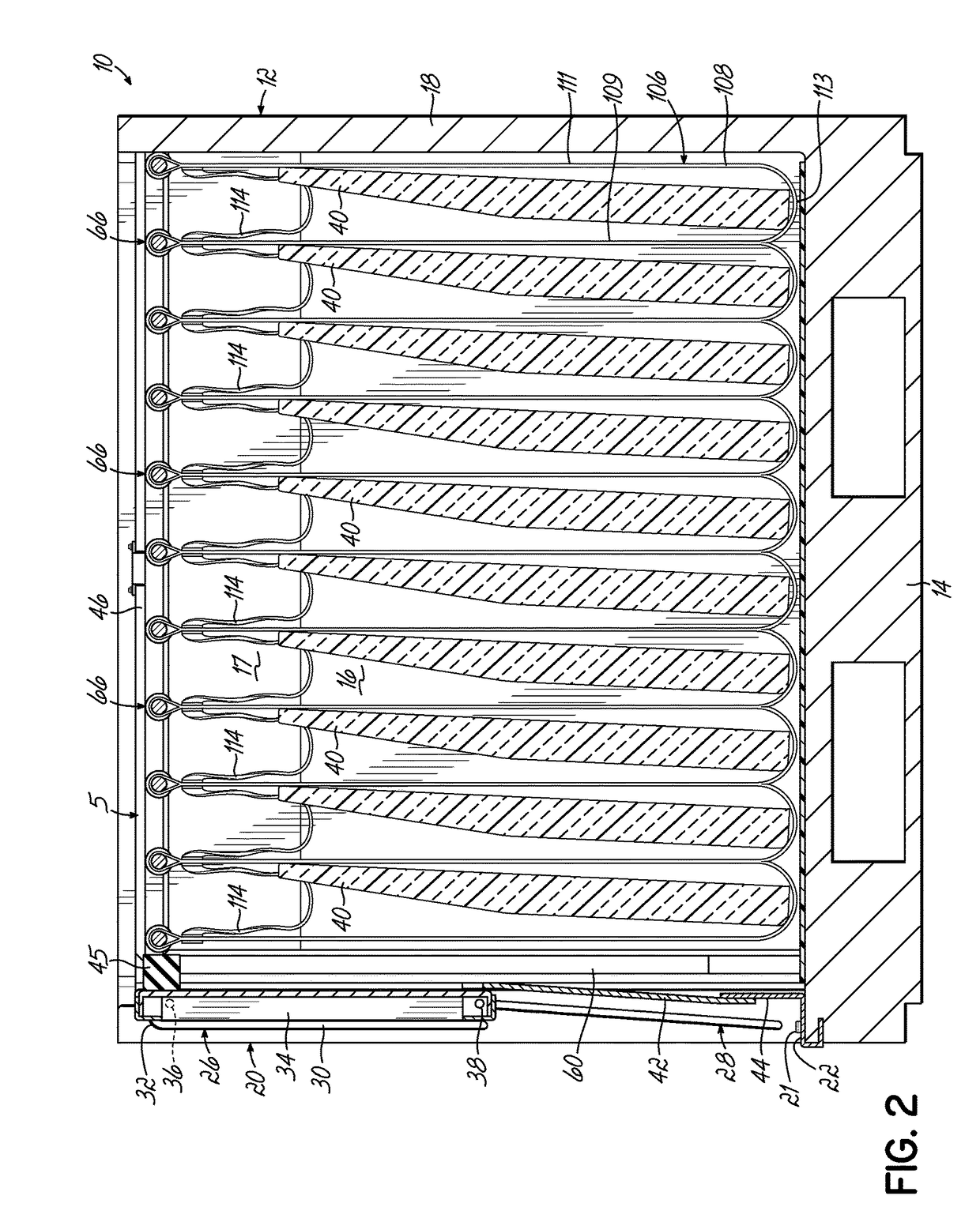
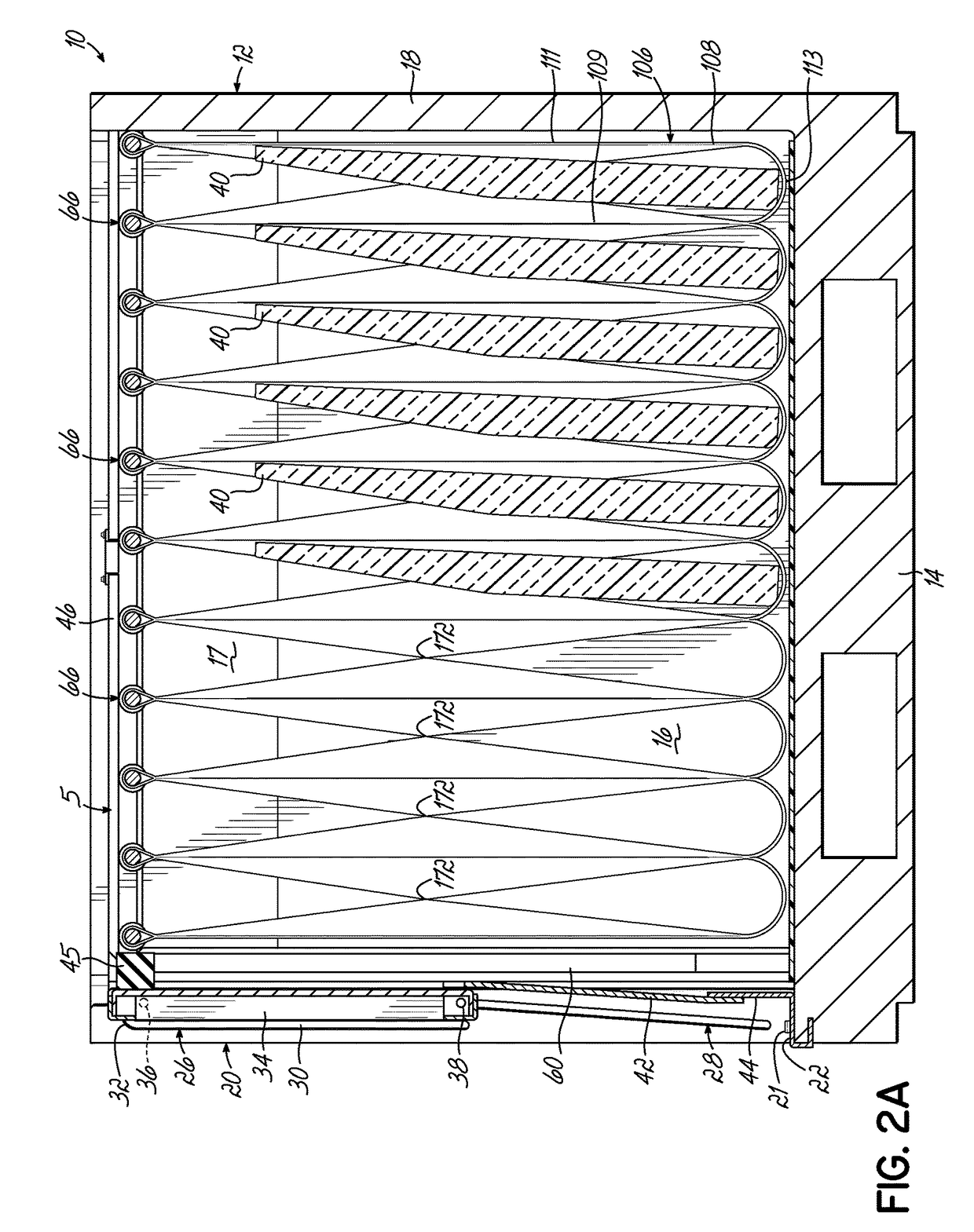
[0093]As shown in FIG. 2, a bumper 17 may be secured to each of the side walls 16 (only one being shown). Each bumper 17 functions to protect the products 40 from contacting the side walls 16 and being scratched or damaged in some fashion. The bumpers may be made of foam or any other suitable material. If desired, the bumpers may be omitted.

[0094]Although one specific shape of product 40 is il...


PUM


Abstract

A container for holding product therein during shipment and being returned for reuse has guides containing generally L-shaped slotted tracks having horizontal and vertical portions. A plurality of dunnage supports extend between the tracks. Dunnage is suspended by the dunnage supports. The dunnage supports have narrowed portions engaged with the slotted tracks.

Description

CROSS REFERENCE TO RELATED APPLICATIONS[0001]This application is a continuation of U.S. patent application Ser. No. 14 / 539,339 filed Nov. 12, 2014, which is a continuation-in-part of U.S. patent application Ser. No. 13 / 896,675 filed May 17, 2013, now U.S. Pat. No. 9,233,790, which is a continuation-in-part of U.S. patent application Ser. No. 13 / 616,635 filed Sep. 14, 2012, now U.S. Pat. No. 9,004,307. U.S. patent application Ser. No. 14 / 539,339 filed Nov. 12, 2014 is also a continuation-in-part of U.S. patent application Ser. No. 13 / 888,686 filed May 7, 2013, now U.S. Pat. No. 9,010,563, which is a continuation-in-part of U.S. patent application Ser. No. 13 / 616,635 filed Sep. 14, 2012, now U.S. Pat. No. 9,004,307. All of these applications are fully incorporated by reference herein.FIELD OF THE INVENTION[0002]The present invention relates to containers for use in shipping and, more particularly, to containers with movable members for supporting product.BACKGROUND OF THE INVENTION[00...

Claims


Application Information

Patent Timeline
Patent Type & Authority Applications(United States)
IPC IPC(8): B65D88/54B65D19/06B65D90/04B65D85/68B65D19/38B65D90/00B65D88/12B65D25/00
CPCB65D88/546B65D2585/6887B65D19/06B65D25/005B65D85/68B65D19/385B65D90/008B65D90/046B65D2519/00024B65D2519/00069B65D2519/00174B65D2519/00164B65D2519/00034B65D2519/00273B65D2519/00288B65D2519/00422B65D2519/00502B65D2519/00532B65D2519/00805B65D88/12B65D19/44B65D81/05B65D2519/00044B65D2519/00059B65D2519/00184B65D2519/00233B65D2519/00268B65D2519/00293B65D2519/00318B65D2519/00323B65D2519/00333B65D2519/00497B65D2519/00562B65D2519/00611B65D2519/00621B65D2519/00666B65D2519/00701B65D2519/0082B65D2585/6882B65D88/54B65D90/0046
Inventor BRADFORD, JUDSON A.BURNS, ALLEN L.SANGER, MATTHEW S.DOBRINSKI, BRIAN T.BRUINSMA, ERIC S.BUBLITZ, TIMOTHY A.
Owner BRADFORD CO
Why Eureka
Try Eureka