Rack structure

Inactive Publication Date: 2017-08-17
LIU YUNG JUI
View PDF0 Cites 2 Cited by
  • Summary
  • Abstract
  • Description
  • Claims
  • Application Information

AI Technical Summary

Benefits of technology

[0006]The primary object of the present invention is to provide a rack structure for holding or storing things. The rack structure includes a coupling member to connect support members at the same side of the bottom of the rack

Problems solved by technology

The user may be hurt by the pointed end, and the appearance is not pleasing to the eyes.
Due to the large number of the hard rods 51, the connection of th

Method used


Image

  • Rack structure
  • Rack structure
  • Rack structure

Examples


Example

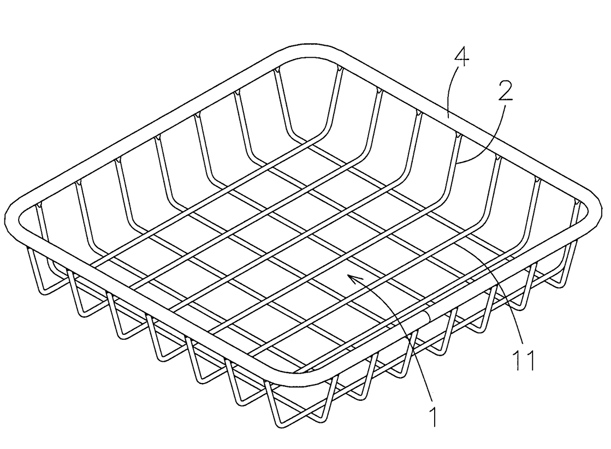
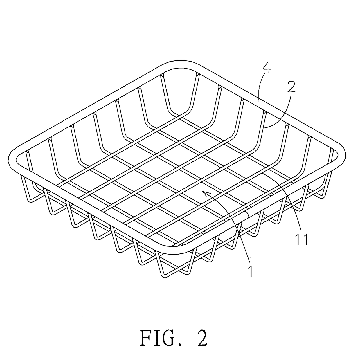
[0018]Referring to FIG. 2 and FIG. 3, a rack in accordance with an embodiment of the present invention comprises a bottom 1 for holding or storing things. In this embodiment, the bottom 1 comprises a plurality of rods 11. The rods 11 are arranged in a crisscross manner to form a flat netted configuration. Two ends of each rod 1 extend to the circumferential portion of the bottom 1, defined as support members 2. Each support member 2 is bent to extend upward from the bottom 1. Accordingly, through the arrangement of the support members 2 and the bottom 1, a basket configuration is formed.

[0019]As shown in FIG. 3, the support members 2 at the same side of the bottom 1 are provided with a coupling member 3. As shown in FIG. 3b, the coupling member 3 is in a strip shape. Two long sides of the coupling member 3 are defined as first wing portions 31. The two first wing portions 31 are curved downward. The coupling member 3 is formed with a plurality of through holes 32 corresponding to th...


PUM


Abstract

A rack structure includes a bottom, a coupling member, and a side frame. The bottom has rod-shaped support members extending out from the circumference of the bottom. The coupling member has through holes for insertion of the support members. A distal end of each support member is provided with a stop block having an outer diameter greater than the through holes. The side frame has an accommodation room therein. One side of the side frame has an opening. The side frame has a pair of hook portions located at two sides of the opening and extending toward the accommodation room. The coupling member connected with the distal end of each support member is inserted through the opening into the accommodation room of the side frame. The hook portions of the side frame enable the coupling member to lean against the stop block of each support member tightly.

Description

FIELD OF THE INVENTION[0001]The present invention relates to a rack for holding or storing things, and more particularly to a hard netted rack for holding or storing things.BACKGROUND OF THE INVENTION[0002]FIG. 1 shows a conventional rack which is a basket composed of a plurality of crisscrossed hard rods 51. The distal ends 52 of the hard rods 51 are hooped with a side frame 53, and the distal ends 52 of the hard rods 51 are fixed to the side frame 53 respectively to ensure the stability of the basket.[0003]Since the conventional rack is used as a daily article, the side frame 53 is simply fixed to the distal end 52 of each hard rod 51 in order to reduce the cost because of its simple structure and low sale price. It can be seen that although the distal ends 52 of the hard rods 51 are fixed to the side frame 53, the distal ends 52 of the hard rods 51 protrude out of the side frame 53 to form pointed ends. The user may be hurt by the pointed end, and the appearance is not pleasing t...

Claims


Application Information

Patent Timeline
IPC IPC(8): A47B47/02A47B55/02
CPCA47B55/02A47B47/027A47F3/147B65D7/20B65D7/14
Inventor LIU, YUNG-JUI
Owner LIU YUNG JUI
Why Eureka
Try Eureka