Optical equipment for observation of the iridocorneal zone, methods of measuring and/or evaluating the iridocorneal zone

Active Publication Date: 2017-08-17
NIDEK CO LTD
View PDF4 Cites 12 Cited by
  • Summary
  • Abstract
  • Description
  • Claims
  • Application Information

AI Technical Summary

Benefits of technology

The patent aims to improve the use of gonioscopy, a technique used by ophthalmic professionals to diagnose glaucoma. The patent proposes to provide better and faster diagnosis by making the use of gonioscopy more accessible to people with less skills. The patent suggests capturing images of the eye simultaneously or sequentially over a short period of time. This would help to capture more information and make the diagnosis more accurate.

Problems solved by technology

Moreover, this contact procedure implies several risks, including corneal scratches, and requires a skilled operator to be carried out; the entire process also requires a careful sterilization of the instrument and to anaesthetize the patient eye.

Method used


Image

  • Optical equipment for observation of the iridocorneal zone, methods of measuring and/or evaluating the iridocorneal zone
  • Optical equipment for observation of the iridocorneal zone, methods of measuring and/or evaluating the iridocorneal zone
  • Optical equipment for observation of the iridocorneal zone, methods of measuring and/or evaluating the iridocorneal zone

Examples


Embodiment Construction

[0027]The following detailed description of exemplary embodiments refers to the accompanying drawings.

[0028]The following detailed description does not limit the present invention. Instead, the scope of the present invention is defined by the appended claims.

[0029]Reference throughout the specification to “one embodiment” or “an embodiment” means that a particular feature, structure, or characteristic described in connection with an embodiment is included in at least one embodiment of the subject matter disclosed. Thus, the appearance of the phrases “in one embodiment” or “in an embodiment” in various places throughout the specification is not necessarily referring to the same embodiment. Further, the particular features, structures or characteristics may be combined in any suitable manner in one or more embodiments.

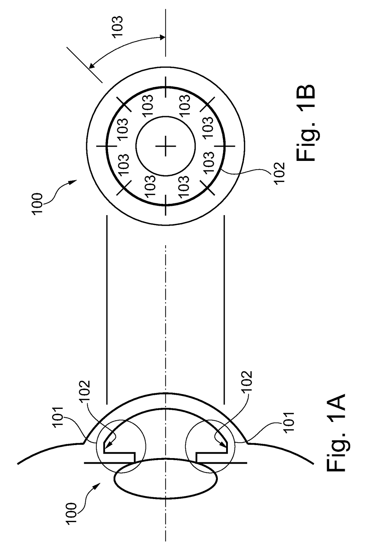
[0030]In FIG. 1, the eye is labeled 100 and its iridocorneal annular zone 101; considering FIG. 1A, as known, the iridocorneal annular zone 101 is substantially delimite...


PUM


Abstract

An optical equipment suitable for observation of an iridocorneal annular zone of an eye including: an illumination assembly, including at least one illumination electric device for illuminating the zone with a plurality of illumination optical paths for illumination light beams going to a corresponding plurality of sub-portions, an image capturing assembly, including at least one image capturing electric device for capturing images of the zone with a plurality of imaging optical paths for imaging light beams coming from a corresponding plurality of sub-portions, and a front optical assembly having a front surface located close to front surface of an eye, a rear surface located far from front surface of an eye, and including a central portion between the front and rear surfaces and a lateral portion around the central portion; the front optical assembly is stationary; all imaging optical paths pass through central portion between the front and rear surfaces.

Description

TECHNICAL FIELD[0001]The present invention relates to “gonioscopy”, more in particular to an optical equipment suitable for observation of at least a portion of an iridocorneal annular zone of an eye and to measuring and / or evaluating methods enabled by such equipment.BACKGROUND ART[0002]Gonioscopy is an eye examination that is very useful and effective in monitoring and diagnosing various eye conditions associated in particular to glaucoma; it is used by ophthalmologists and optometrists as a primary examination for glaucomatous patients; typically, it is carried out through the use of an indirect gonioscopic lens.[0003]The instruments that are commercially available at present have some drawbacks. They allow only human interpretation. They allow to observe only few and / or limited portions of an iridocorneal zone of an eye; therefore, if an ophthalmologist wants to observe the entire iridocorneal site, he must apply and remove the instrument, in direct contact with the patient eye....

Claims


Application Information

Patent Timeline
IPC IPC(8): A61B3/117A61B3/00A61B3/14
CPCA61B3/117A61B3/0025A61B3/0091A61B3/14
Inventor TANASSI, CESAREBUSCEMI, PHILCARRARO, FEDERICODE GIUSTI, ANDREAMINOZZI, MATTIAPAJARO, SIMONEPASCOLINI, MICHELECODOGNO, NICOLA
Owner NIDEK CO LTD
Why Eureka
Try Eureka