Expander device, porous film producing apparatus, and porous film producing method

Inactive Publication Date: 2017-08-24
SUMITOMO CHEM CO LTD
View PDF3 Cites 1 Cited by
  • Summary
  • Abstract
  • Description
  • Claims
  • Application Information

AI Technical Summary

Benefits of technology

The present invention provides an expander device, a porous film producing apparatus, and a porous film producing method that prevents wear powder from sticking to the film.

Problems solved by technology

The use of an expander roller, however, involves friction between the expander roller and the porous film.
This friction wears out the porous film, leaving wear powder.
This may hinder a later step.

Method used


Image

  • Expander device, porous film producing apparatus, and porous film producing method
  • Expander device, porous film producing apparatus, and porous film producing method
  • Expander device, porous film producing apparatus, and porous film producing method

Examples


embodiment 1

[0027]

[0028]A nonaqueous electrolyte secondary battery, typically a lithium-ion secondary battery, has a high energy density, and is therefore currently widely used not only as batteries for use in devices such as personal computers, mobile phones, and mobile information terminals, and for use in moving bodies such as automobiles and airplanes, but also as stationary batteries contributing to stable power supply.

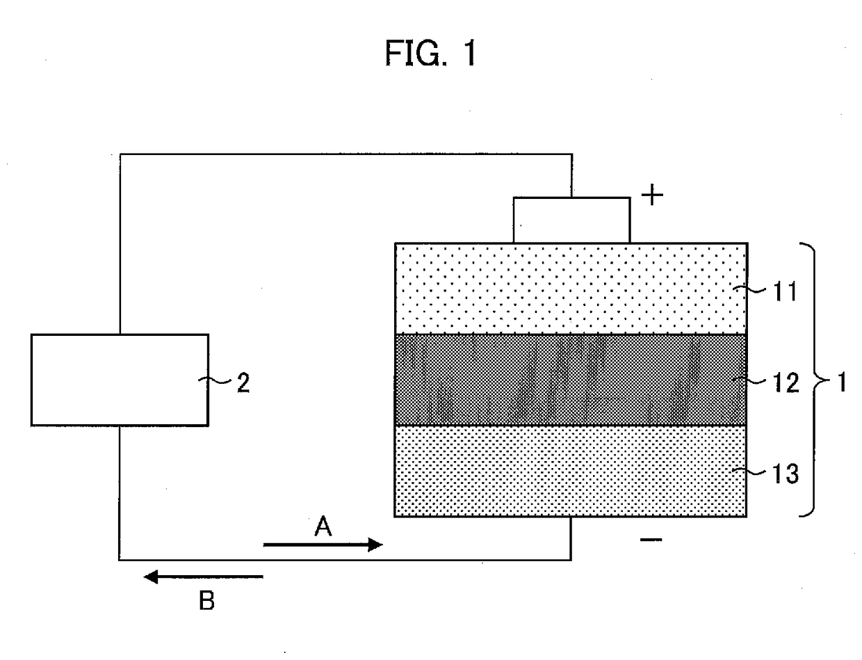
[0029]FIG. 1 is a diagram schematically illustrating a cross-sectional configuration of a lithium-ion secondary battery 1.

[0030]As illustrated in FIG. 1, the lithium-ion secondary battery 1 includes a cathode 11, a separator 12, and an anode 13. Between the cathode 11 and the anode 13, an external device 2 is connected outside the lithium-ion secondary battery 1. While the lithium-ion secondary battery 1 is being charged, electrons move in a direction A. Meanwhile, while the lithium-ion secondary battery 1 is being discharged, electrons move in a direction B.

[0031]

[0032]The ...

embodiment 2

[0084]The following description will discuss another embodiment of the present invention with reference to FIGS. 8 and 9. Note that, for convenience of explanation, identical reference numerals are given to members which have respective functions identical with those described in Embodiment 1, and descriptions of the respective members are omitted.

[0085]FIG. 8 is a diagram schematically illustrating a state in which a porous film is transferred with use of an expander device of Embodiment 2.

[0086]As illustrated in FIG. 8, a separator producing apparatus 130 of Embodiment 2 includes an expander device 120. The expander device 120 includes an expander roller 21 and a sucking device 122.

[0087]The sucking device 122 has a tip that serves as a sucking port (sucking section, foreign matter removing section) configured to suck foreign matter such as wear powder of the porous film F. The sucking device 122 is positioned near the expander roller 21 in its longitudinal direction at a portion ...

embodiment 3

[0095]The following description will discuss another embodiment of the present invention with reference to FIGS. 10 to 12. Note that, for convenience of explanation, identical reference numerals are given to members which have respective functions identical with those described in Embodiment 1 or 2, and descriptions of the respective members are omitted.

[0096]FIG. 10 is a diagram schematically illustrating a state in which a porous film is transferred with use of an expander device of Embodiment 3.

[0097]As illustrated in FIG. 10, a separator producing apparatus 230 of Embodiment 3 includes an expander device 220. The expander device 220 includes an expander roller 21 and a scraper 222.

[0098]The scraper 222 has a tip that serves as a contact section (foreign matter removing section) configured to scrape foreign matter such as wear powder of the porous film F. The tip of the scraper 222 is in contact with the expander roller 21 in its longitudinal direction at a portion of the outer p...


PUM

PropertyMeasurementUnit
Widthaaaaaaaaaa
Tensionaaaaaaaaaa

Abstract

To prevent wear powder from adhering to a film, an expander roller (21) is used that extends in the width direction of a porous film (F) and that is configured to apply a tension to the porous film (F) in the width direction, and foreign matter adhering to the expander roller (21) is removed from a portion of the outer peripheral surface of the expander roller (21) at which portion the expander roller (21) is in no contact with the porous film (F).

Description

CROSS-REFERENCE TO RELATED APPLICATIONS[0001]This Nonprovisional application claims priority under 35 U.S.C. §119 on Patent Application No. 2016-030299 filed in Japan on Feb. 19, 2016, the entire contents of which are hereby incorporated by reference.TECHNICAL FIELD[0002]The present invention relates to an expander device, a porous film producing apparatus, and a porous film producing method.BACKGROUND ART[0003]A heat-resistant separator (porous film) for a lithium-ion secondary battery is produced as follows: While a porous film as a base material is being transferred with use of a transfer system including a transfer roller, the porous film undergoes steps such as (i) a coating step of coating a surface of the porous film with a coating material to be used as a heat-resistant layer and (ii) a drying step of drying the coating material.[0004]The transfer system includes (i) a driving roller configured to apply a transfer tension to a porous film, (ii) a guide roller configured to a...

Claims


Application Information

Patent Timeline
IPC IPC(8): B29C55/08B29C33/76H01M2/16B29C33/72H01M10/0525H01M2/14H01M50/403H01M50/417H01M50/423
CPCB29C55/08H01M10/0525H01M2/145B29L2031/3468B29C33/72B29C33/76H01M2/1653B65H20/02B65H27/00B65H2701/1133B65H2701/1752H01M50/403H01M50/423H01M50/417B65H23/0258B65H2801/72B65H23/0256Y02E60/10B29C43/46B29C2043/466B29C2043/461B29K2715/003
Inventor WATANABE, KOICHIROTAKAOKA, YUJI
Owner SUMITOMO CHEM CO LTD
Why Eureka
Try Eureka