Ferrite core material for resin-filled type carrier, resin-filled type carrier, and electrophotographic developer using the carrier

a technology of electrophotographic developer and carrier, which is applied in the field of ferrite core material for resin-filled type carrier, resin-filled type carrier, electrophotographic developer using the carrier, can solve the problems of reducing the surface area of the available carrier, reducing the friction chargeability of toner particles, etc., to achieve excellent fluidity, low true density, and long life

Active Publication Date: 2006-11-30
POWDERTECH
View PDF12 Cites 44 Cited by
  • Summary
  • Abstract
  • Description
  • Claims
  • Application Information

AI Technical Summary

Benefits of technology

[0061] The resin-filled type carrier relevant to the present invention has, since filled with a resin, a low true density, an elongated life and an excellent fluidity, and the selection of filling resins makes

Problems solved by technology

However, since such iron powder carriers have high own weights and too high magnetizations, fusion of the toner to the surface of the iron powder carrier, so-called toner spent, becomes liable to occur by mixing and agitation with the toner particles in a development box.
The occurrence of such toner spent reduces the available carrier surface area, becoming liable to decrease the friction chargeability with the toner particles.
Such charge leak breaks electrostatic latent images formed on a photoreceptor, and generates brush strokes and the like on solid parts, causing inferior durability such as hardly providing uniform images.
When the particle size distribution is totally made to be of a small particle size, especially particles on the fine powder side become liable to bring about the phenomenon of the carrier particles scattering or adhering to a photoreceptor, which is a disadvantage of the two-component developer, and induce fatal image faults such as white spots.
Therefore, they have a problem of hardly providing a sufficient image density.
The magnetic powder-dispersed carriers sometimes raise problems that magnetic fine particles are solidified with binder resins, and drop off by the agitation stress and the impacts in developing machines, and that the carriers themselves break possibly due to their low hardness as compared with those of iron powder carriers and ferrite carriers conventionally used.
Then, dropped-off magnetic fine particles and the broken carrier particles adhere to a photoreceptor, and sometimes cause image faults.
Additionally, the magnetic powder-dispersed carriers have a disadvantage of having a high residual magnetization and a high coercive force because of use of fine magnetic particles, and deteriorating the fluidity of the developers.
Especially when magnet brushes are formed on a magnet roll, high-quality images can hardly be obtained, because the fluidity is bad due to the high residual magnetization and coercive force, and bristles of the magnetic brushes are hardened.
Further, even when the carrier leaves the magnet roll, since the carrier magnetic aggregation does not come loose, and the carrier cannot be rapidly mixed with a supplied toner, the rising of the charge quantity is bad, raising a problem of causing image faults such as toner scattering and fogging in images.
Further, although the magnetic powder-dispersed carriers can be fabricated by two methods of the crushing one and the polymerization one, both have a problem of a high producing cost because the crushing method is bad in yield, and the polymerization method is complicated in the producing process.
However, the porosity of about 1,600 cm2/g in BET area as described in the example of the Patent Document cannot provide a sufficiently low specific gravity even when voids are filled with a resin, and cannot

Method used


Image

  • Ferrite core material for resin-filled type carrier, resin-filled type carrier, and electrophotographic developer using the carrier
  • Ferrite core material for resin-filled type carrier, resin-filled type carrier, and electrophotographic developer using the carrier

Examples


example 1

Example 1a

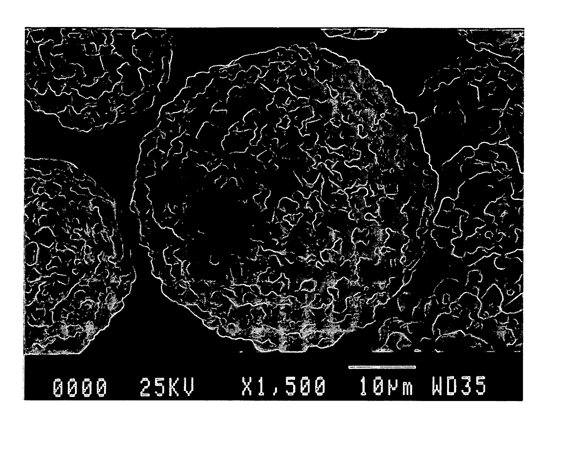
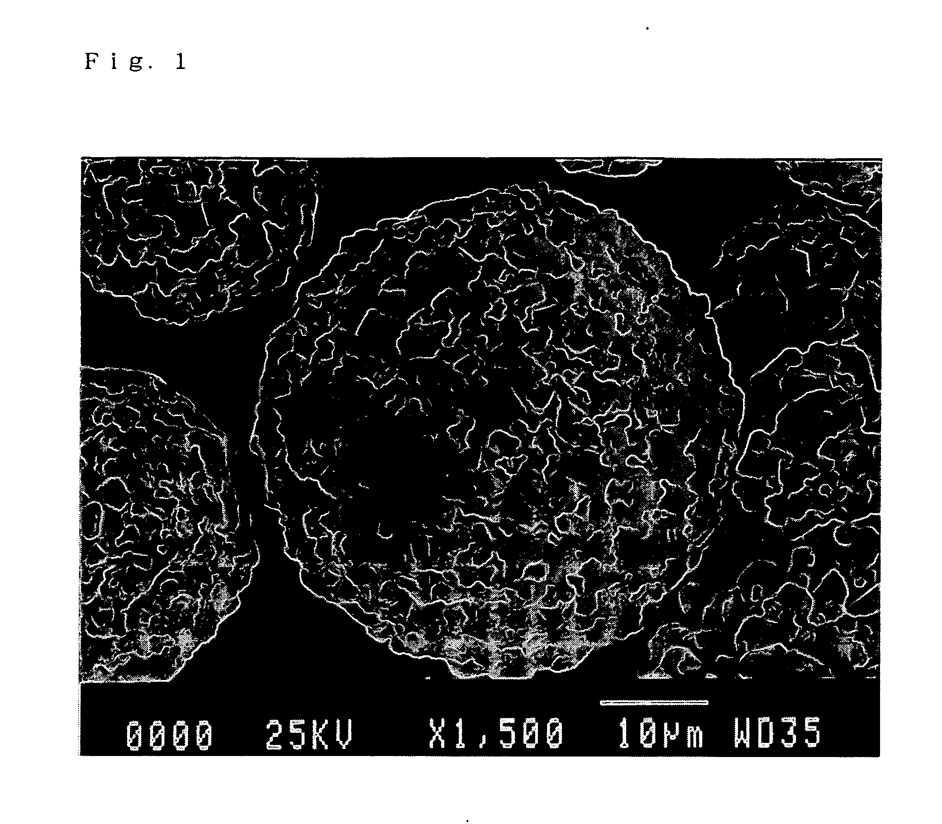
[0154] Raw materials were weighed so as to become MnO: 35 mol %, MgO: 14.5 mol %, Fe2O3: 50 mol % and SrO: 0.5 mol %, mixed with water, and then crushed by a wet media mill for 5 hours to obtain a slurry. The obtained slurry was dried by a spray drier to obtain spherical particles. For adjusting the void fraction and continuous void degree, manganese carbonate as the MnO raw material and magnesium hydroxide as the MgO raw material were used. The particles were adjusted for the particle size, and heated at 950° C. for 2 hours for calcination. Then, for obtaining a suitable fluidity with a comparatively high void fraction, the calcined material was crushed for one hour by a wet ball mill using stainless beads of ⅛ inch in diameter, and further crushed for 4 hours using stainless beads of 1 / 16 inch in diameter. This slurry was added with a dispersant in an appropriate amount, and for the purpose of securing the strength of particles to be granulated and adjusting the void fr...

example 1b

[0155] A core material of ferrite particles was obtained as in Example 1a, but using trimanganese tetraoxide instead of manganese carbonate, the binder to be added of 0.8 wt. %, and zirconia beads of 0.5 mm instead of stainless beads of 1 / 16 inch in diameter, and holding and sintering at a temperature of 1,150° C. at an oxygen concentration of 0.5 vol % for 4 hours in an electric furnace.

example 1c

[0156] A core material of ferrite particles was obtained as in Example 1a, but using manganese dioxide instead of manganese carbonate, and the binder to be added of 0.5 wt. %, and holding and sintering at a temperature of 1,200° C. at an oxygen concentration of 1.5 vol % for 4 hours in an electric furnace.


PUM


Abstract

A ferrite core material for a resin-filled type carrier, and a resin-filled type carrier which is used as an electrophotographic developer by mixing a toner, sufficiently secure the image density, have no carrier adhesion and can maintain high-quality images over a long period, and an electrophotographic developer using the carrier, are provided. A ferrite core material for a resin-filled type carrier characterized in a void fraction of 10 to 60%, a resin-filled type carrier filled in the carrier core material with a resin, and an electrophotographic developer composed of the resin-filled type carrier and a toner, are provided.

Description

BACKGROUND OF THE INVENTION [0001] 1. Field of the Invention [0002] The present invention relates to a ferrite core material for a resin-filled type carrier and a resin-filled type carrier used for a two-component electrophotographic developer used in copying machines, printers and the like, and an electrophotographic developer using the carrier, particularly to a ferrite core material for a resin-filled type carrier and a resin-filled type carrier which have a low true density, an elongated life, an easily controllable charging amount, etc. and a high strength, and generate little cracking, deformation and melting by heat and impact, and an electrophotographic developer using the carrier. [0003] 2. Description of the Related Art [0004] The electrophotographic developing method is one which develops images by adhering toner particles in a developer to electrostatic latent images formed on a photoreceptor, and the developers used in this method are classified into a two-component dev...

Claims


Application Information

Patent Timeline
IPC IPC(8): G03G9/107
CPCG03G9/0833G03G9/0835G03G9/0836G03G9/0837G03G9/1137G03G9/0839G03G9/1131G03G9/1136G03G9/0838
Inventor KOBAYASHI, HIROMICHIITAGOSHI, TSUYOSHISUWA, TOMOYUKIHONJO, TOSHIO
Owner POWDERTECH
Why Eureka
Try Eureka