
Method and test tool for adjusting brush holders in slip ring systems

Active Publication Date: 2017-08-24
VESTAS WIND SYST AS
View PDF7 Cites 0 Cited by
  • Summary
  • Abstract
  • Description
  • Claims
  • Application Information

AI Technical Summary

Benefits of technology

[0015]The test tool can be used for adjusting the brush holders on either generators or motors which are equipped with slip ring systems. Some benefits are t

Problems solved by technology

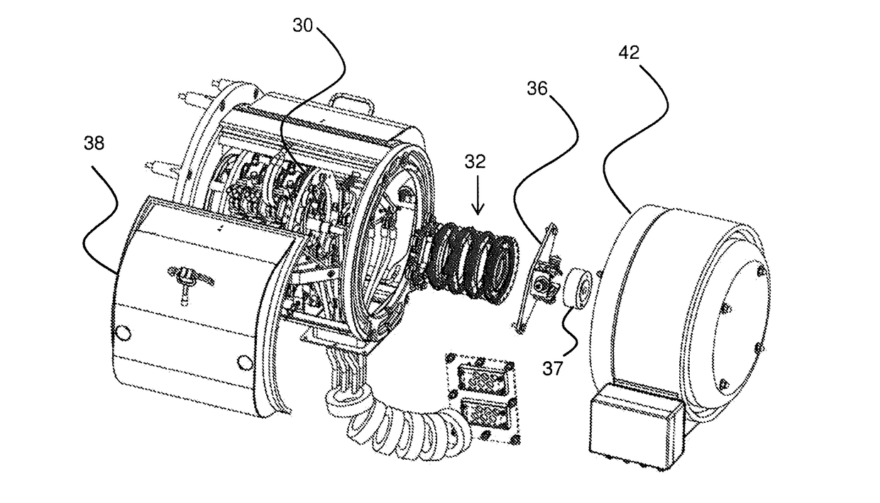
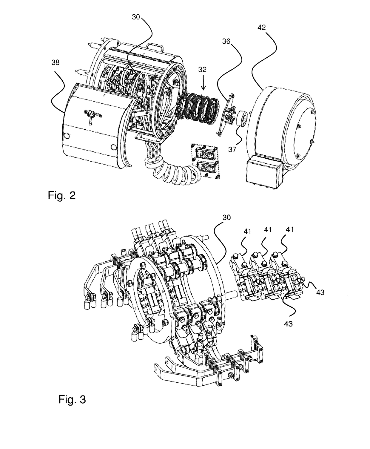
Indeed, due to the limited visual access to the bearing surfaces and as should be clear by looking at e.g. FIGS. 2 and 3, it may be difficult to ascertain visually whether there is full contac

Method used


Image

  • Method and test tool for adjusting brush holders in slip ring systems
  • Method and test tool for adjusting brush holders in slip ring systems
  • Method and test tool for adjusting brush holders in slip ring systems

Examples


Example

[0026]The accompanying drawings are not intended to be drawn to scale. In the drawings, each identical or nearly identical component that is illustrated in various figures may be represented by a like numeral. For purposes of clarity, not every component may be labelled in every drawing.

DETAILED DESCRIPTION OF THE DRAWINGS

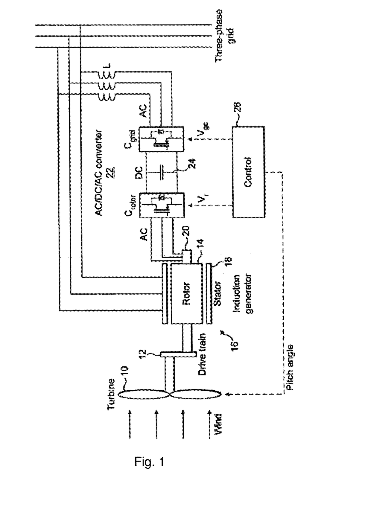
[0027]FIG. 1 shows a schematic view of a wind turbine. Turbine blades 10 are driven by incident wind and, via a drive train 12, cause rotation of an electrical rotor 14 of a three phase induction generator 16. A stator 18 has a three phase winding which is connected directly to the transmission grid and the three phase rotor winding is connected via a slip ring and brush assembly 20 to the rotor side Crotor of a converter 22, the grid side of which Cgrid is coupled via coupling inductors L to the grid. Crotor and Cgrid are AC / DC converters with DC voltage being provided by a capacitor 24 arranged between the converters. A control system 26 generates a pitch angle c...


PUM


Abstract

The invention relates to a method of adjusting a brush holder (41) of a slip ring and brush assembly comprising at least one slip ring (50) with a radius of curvature R. With the method a test tool (80) is used to simulate a brush in the brush holder with the important difference that the test tool is able to indicate to the operator whether full contact between the slip ring and the contact surface of the test tool is obtained.

Description

FIELD OF THE INVENTION[0001]The present invention relates to a test tool for adjusting the brush holders on either generators or motors which are equipped with slip ring systems.BACKGROUND OF THE INVENTION[0002]A wind turbine converts wind power into electrical energy through a generator driven by the blades of the wind turbine under windy conditions. In some wind turbines, the generator comprises a stator and a rotor both having multiphase windings, such as a double-fed induction generator, a cascade-regulated generator, an induction or a synchronic generator, or even a dc generator.[0003]When having a rotor rotating in relation to a stator of a generator, electricity has to be transferred to or from the rotor. Electricity may be transferred by means of a slip ring assembly also called a rotary electrical interface, rotating electrical connector, collector, or swivel or electrical rotary joint, enabling the rotor to receive or return electricity while rotating in relation to the st...

Claims


Application Information

Patent Timeline
IPC IPC(8): H02K5/14H01R39/08H01R39/40H02K15/00H01R39/38
CPCH02K5/141H02K15/00H01R39/08H01R39/40H01R39/385H01R39/38H02K2213/09
Inventor SORENSEN, KIM SVEINSSONKRISTENSEN, KIM
Owner VESTAS WIND SYST AS
Learn More