A cap for a container and a package comprising such a cap

Active Publication Date: 2017-09-14
SOC DES PROD NESTLE SA
View PDF12 Cites 2 Cited by
  • Summary
  • Abstract
  • Description
  • Claims
  • Application Information

AI Technical Summary

Benefits of technology

This patent describes a cap that can be easily attached to a container by putting a locking flap in a position. The cap has a locking flange that engages with an undercut near the mouth of the container to create a secure seal. The cap is designed to work with a preform that has been molded to fit the cap, allowing for a tight and secure seal. This invention simplifies the attachment process and ensures a proper seal.

Problems solved by technology

However, this also means that the strength of the joint between cap and container is weak.
As a result, the cap may be easily dislodged when the cap or container are subjected to external shocks and impacts (particularly from the lateral direction) that may be encountered during transport and use of the container, leading to leakage and spills.
However, screw-on caps are less than ideal, in that they require a large amount of force to open and close.
This poses difficulties to children, the elderly, and others who do not have sufficient strength or manual dexterity to properly tighten and loosen such a closure.
Moreover, the provision of threads in the cap and on the neck of the container requires an increased level of precision in the manufacture of both relative to other types of closures, increasing the cost of the container.

Method used


Image

  • A cap for a container and a package comprising such a cap
  • A cap for a container and a package comprising such a cap
  • A cap for a container and a package comprising such a cap

Examples


first embodiment

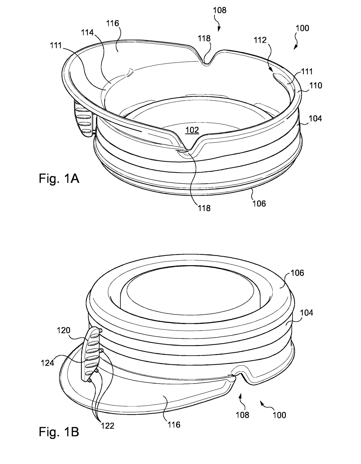
[0056]FIGS. 1A & 1B are bottom and top perspective views, respectively, of a cap according to the invention. Of course, it will be understood that the cap depicted in FIGS. 1A & 1B is intended to be attached to a container, and as such for the purposes of this document orientative terms such as “top” and “bottom” shall be assumed to be as for a cap which is attached to an upright container.

[0057]In FIG. 1A, the cap 100 comprises globally a disc-shaped top section 102 and an annular side section 104. The annular side section 104 extends from the perimeter 106 of the disc-shaped top section 102 in a substantially perpendicular direction, with the result that the cap 100 is of a generally cylindrical form, with one open end 108 opposite the disc-shaped top section 102 which accommodates a neck of a container (not shown) to which the cap 100 is attached. The open end 108 is delimited by the rim 110 of the cap 100, said rim 110 constituting an extremity of the annular side section 104 op...

second embodiment

[0096]FIGS. 4A & 4B are perspective views of a cap 400 according to the invention. FIG. 4A depicts the cap 400 wherein a locking flap 402 thereof is disposed in a locked first position, away from a disc-shaped top section 401 and an annular side section 404.

[0097]The cap 400 of FIGS. 4A & 4B is similar to that presented in the preceding Figures, except that the locking flap 402 extends about the entire circumference of the annular side section 404 of the cap 400. Moreover, the locking flange (not pictured) extends about the entire circumference of the annular side section 404 as well; the entirety of the locking flange is therefore mobile along with the locking flap 402. When disposed in the locked first position, the locking flap 402 will sit against an upper portion 406 of a container 408; preferably, the locking flap 402 is biased so as to press against the shoulder 406, which will help to avoid the locking flap 402 from catching on objects it may come into contact with, and ther...


PUM

PropertyMeasurementUnit
Angleaaaaaaaaaa
Angleaaaaaaaaaa
Angleaaaaaaaaaa

Abstract

A cap (100) for a container comprises a disc-shaped top section (102), an annular side section (104) projecting from said disc-shaped top section (102), and a locking flange (111) disposed at an extremity of said annular side section (104) opposite said disc-shaped top section (102), and further comprises a locking flap (116) extending from said annular side section (104), which is mobile between a locked first position wherein a portion (114) of the locking flange (111) extends inwardly from the annular side section (104), and an unlocked second position wherein the locking flange (111) is at least partially recessed relative to the annular side section (104).

Description

FIELD OF THE INVENTION[0001]The present invention concerns a cap for a container, as well as a package comprising such a container.BACKGROUND OF THE INVENTION[0002]In the packaging arts, it is generally known to provide resealable closures on containers whose contents are not necessarily consumed all at once. They are used for packaging a wide variety of products, and are notably favoured for beverages and other comestibles.[0003]A number of different kinds of resealable closures are known, for instance swinging lever closures, caps, and sliding push-pull closures. Among such closures, caps are regarded as particularly advantageous in that the consumer may open, re-seal, and re-open the container without the need of tools. Of these, the two types which command the overwhelming majority of market share are the press-on snap cap and the screw-on cap.[0004]Snap-caps are generally flat and fabricated from a flexible plastic, and typically comprise an annular groove disposed on a lower s...

Claims


Application Information

Patent Timeline
IPC IPC(8): B65D45/20B29B11/14B29C49/00B65D41/18B65D1/02
CPCB65D45/20B65D41/185B65D1/0246B29L2031/712B29B11/14B29B2911/14553B29C49/0073B65D43/0256B29C49/071B29C2949/0715B29C2949/0797
Inventor CERVENY, JEAN-PAUL
Owner SOC DES PROD NESTLE SA
Why Eureka
Try Eureka