
Scanning probe microscope and probe contact detection method

Active Publication Date: 2017-10-05
HITACHI HIGH TECH SCI CORP
View PDF28 Cites 5 Cited by
  • Summary
  • Abstract
  • Description
  • Claims
  • Application Information

AI Technical Summary

Benefits of technology

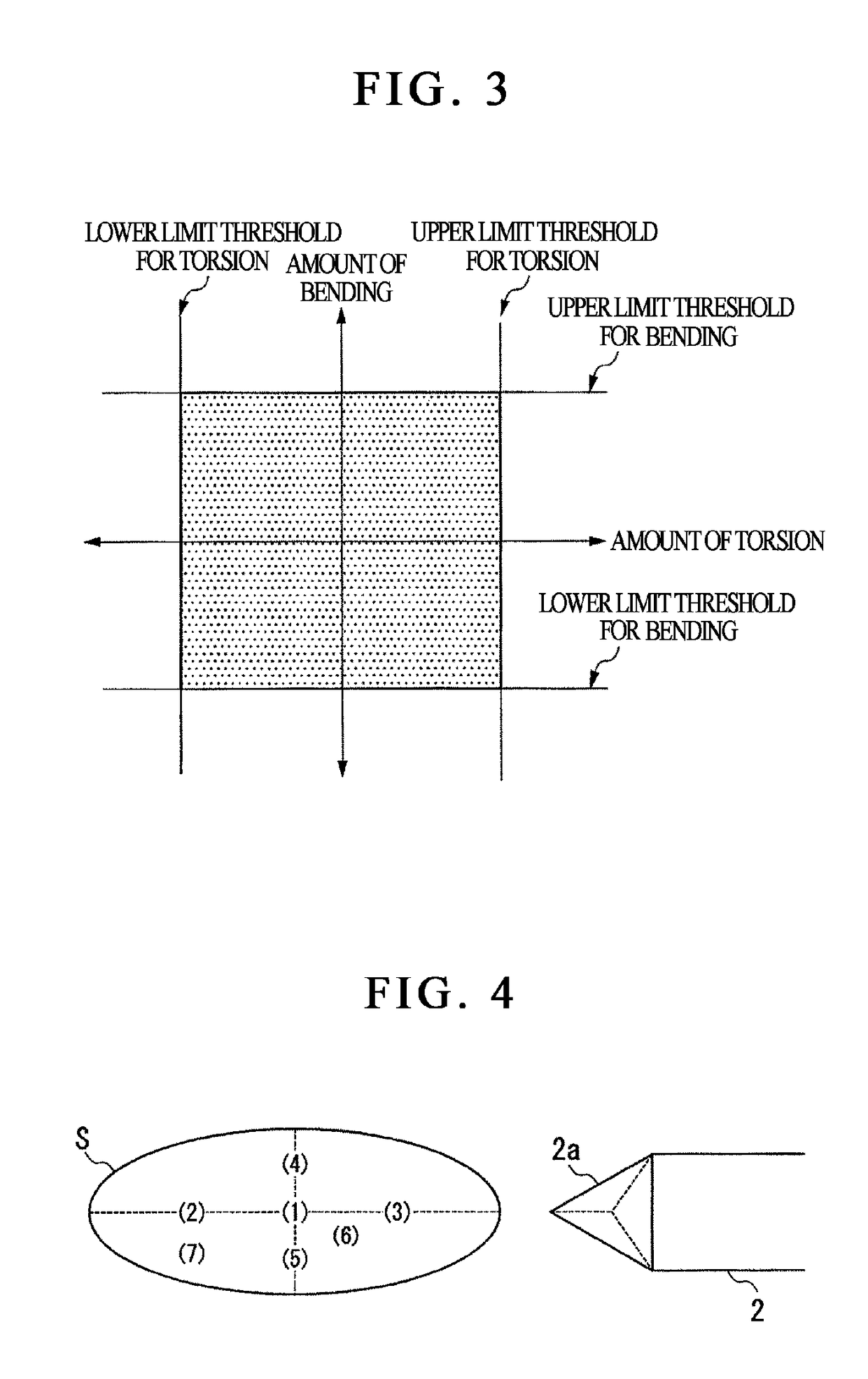
The present invention is a scanning probe microscope and a probe contact detection method that can improve the amount of change in force value when the sample surface is inclined. It uses torsion and bending as deformation of the cantilever to detect the contact between the probe and the sample surface, and then uses all directions of the upper and lower bending and the left and right torsion from the non-deformation as respective deformation directions. This ensures accurate detection of probe-sample contact, regardless of the sample surface's inclination.

Problems solved by technology

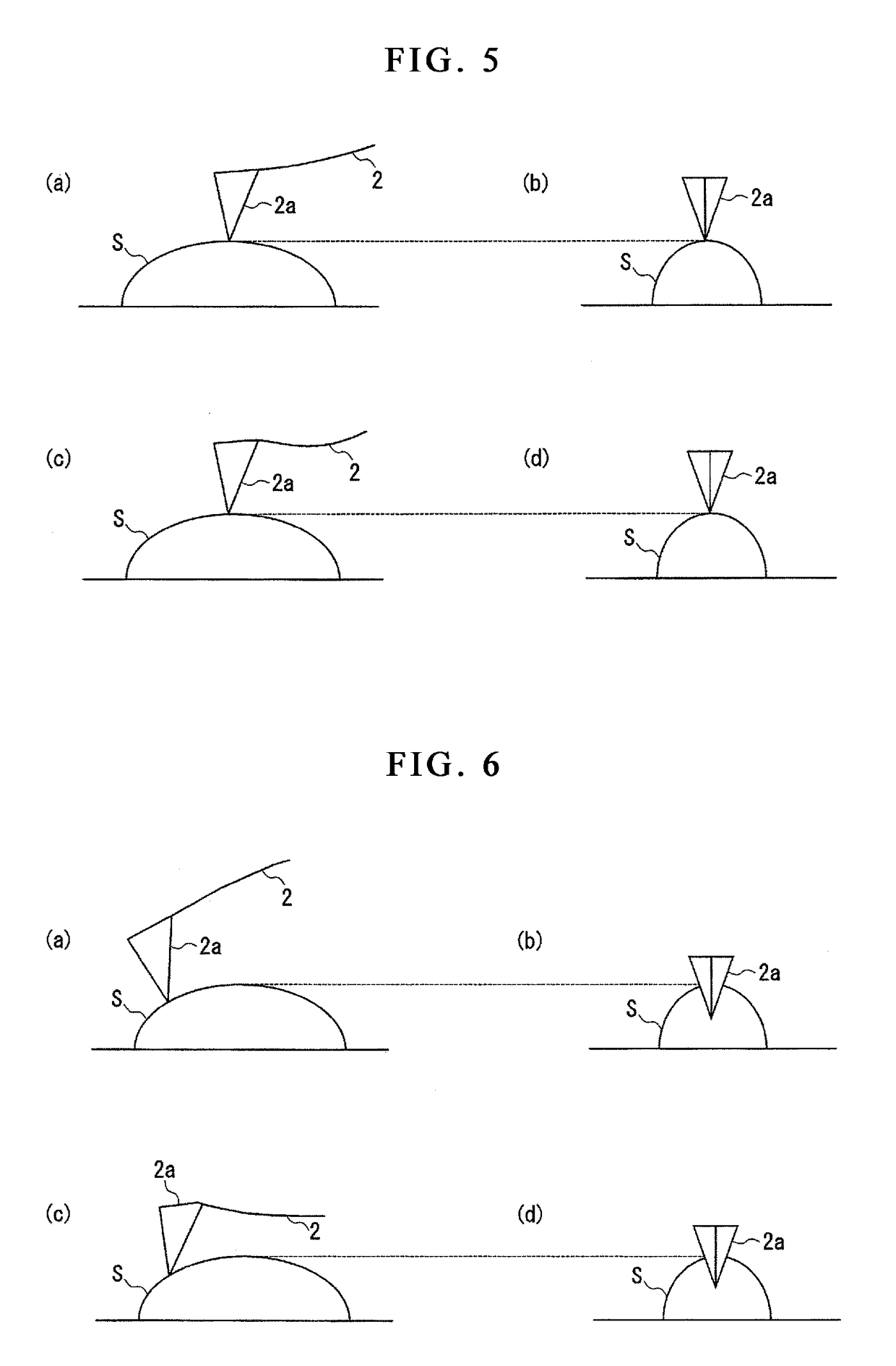
Accordingly, there are cases where along with some error occurring in the shape measurement of the inclined plane of the sample surface, wear of the probe and deformation of the sample can be caused.
Such a problem is not limited to the intermittent measurement method, but common to measurement methods having the step of bringing a probe into contact with a sample surface.

Method used


Image

  • Scanning probe microscope and probe contact detection method
  • Scanning probe microscope and probe contact detection method
  • Scanning probe microscope and probe contact detection method

Examples


Embodiment Construction

[0034]Hereinafter, the present invention will be described through embodiments of the present invention, but the following embodiments do not limit the invention related to the claims. In addition, not all combinations of features described in the embodiments are necessarily essential to solving means of the invention. In the drawings, there are cases where the same or similar parts are denoted by the same reference numerals, omitting their redundant descriptions.

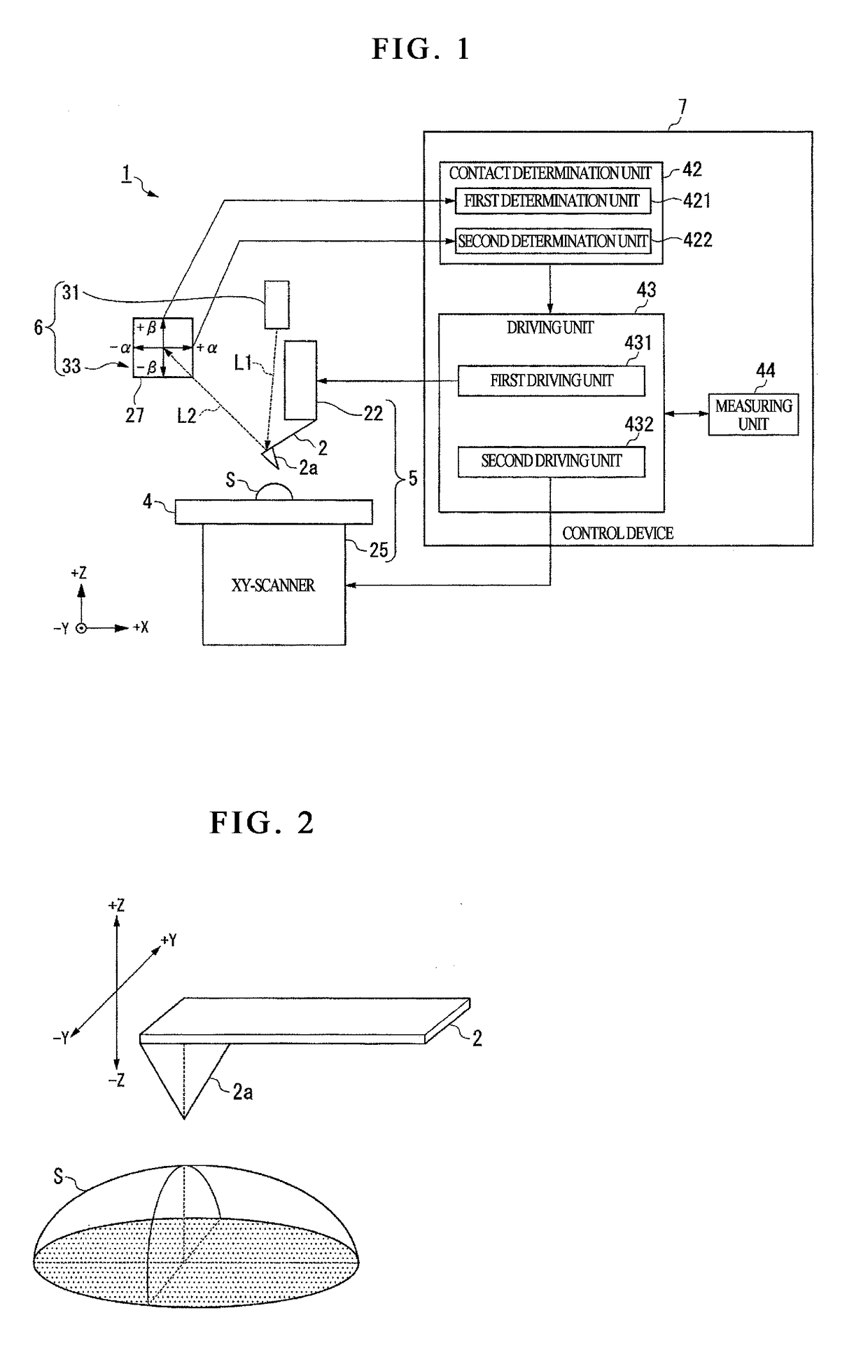
[0035]The scanning probe microscope according to embodiments determines whether the probe is in contact with the sample surface or not, based on the bending amount and torsion amount of the probe by contacting the probe on the sample surface and scanning the sample surface. Hereinafter, the scanning probe microscope according to the embodiment will be described with reference to the drawings.

[0036]FIG. 1 shows an example of a schematic configuration of a scanning probe microscope 1 of the present embodiment. As shown in FIG...


PUM


Abstract

According to this invention, a scanning probe microscope for scanning a surface of a sample with a probe by bringing the probe into contact with the surface of the sample, comprises a cantilever having the probe at its tip; a displacement detection unit to detect both a bending amount and a torsion amount of the cantilever; and a contact determination unit to determine a primary contact of the probe with the surface of the sample, based on the bending amount and the torsion amount detected by the displacement detection unit in all directions from an undeformed condition of the cantilever.

Description

CROSS-REFERENCE TO RELATED APPLICATION[0001]This application claims priority from Japanese Patent Application No. 2016-065007, filed on Mar. 29, 2016, the entire subject matter of which is incorporated herein by reference.BACKGROUND[0002]1. Field of the Invention[0003]The present invention relates to a scanning probe microscope and probe contact sensing method thereof.[0004]2. Description of Related Art[0005]Conventionally, a scanning probe microscope for measuring an uneven (concave-convex) shape of a sample surface by continuously scanning a probe on the sample surface while maintaining the interaction between the probe formed at the tip of the cantilever and the sample (e.g., amplitude of the cantilever or bending of the cantilever) constant is known (see Patent Document 1). However, in the scanning probe microscope described in Patent Document 1, because the probe and the sample are always in contact, there is a possibility that wear of the probe or damage of the sample occurs.[...

Claims


Application Information

Patent Timeline
IPC IPC(8): G01Q10/02
CPCG01Q10/02G01B21/30G01Q20/02G01Q60/00G01Q10/065G01Q20/00G01Q10/04
Inventor SHIGENO, MASATSUGUWATANABE, KAZUTOSHIWATANABE, MASAFUMIYAMAMOTO, HIROYOSHICHINONE, KAZUO
Owner HITACHI HIGH TECH SCI CORP
Learn More