Selective display in a computer generated environment

a computer generated environment and display technology, applied in the field of assisted exploration of computer generated virtual environments, can solve the problems of difficult detection of threats, inability to display original material colours, and objects located in corners, edges or inside the luggage frame, etc., to reduce the demands on system capacity, the effect of reducing the adaptation effort and improving the understanding speed

Active Publication Date: 2017-10-19
FRENCH CIVIL AVIATION UNIVERSITY
View PDF2 Cites 4 Cited by
  • Summary
  • Abstract
  • Description
  • Claims
  • Application Information

AI Technical Summary

Benefits of technology

[0021]The selective omission of certain objects enables a user to better and more quickly understand the contents of the environment, which in turn may lead to reduced demands on system capacity.
[0031]In accordance with a further development of the first aspect, there is provided a further step of receiving a user input determining the orientation, position or field of view of either the virtual camera or the virtual projector. Separate control of the virtual camera and virtual projector opens up new possibilities for exploration of the environment, and inspection of elements of interest from different positions and perspectives, further enabling a user to better and more quickly understand the contents of the environment, which in turn may lead to reduced demands on system capacity.

Problems solved by technology

The exploration of volumetric datasets is not trivial, often requiring extensive knowledge and is usually heavily impacted by the specific needs of users.
Since the resulting X-ray scanned image only contains voxel or pixel densities, it cannot display the original material colours.
Depending on its location inside the luggage, a threat can be difficult to detect.
Objects located in the corners, in the edges or inside the luggage's frame are very difficult to identify.
Contour tree algorithms may be vulnerable to noise, which can be problematic in luggage inspections since dense materials such as steel cause noise by reflecting the X-rays.
A specific difficulty that arises in an environment such as that described with respect to FIG. 1 is that the user's view of a particular article or region of interest will often be obscured by materials of no interest.

Method used


Image

  • Selective display in a computer generated environment
  • Selective display in a computer generated environment
  • Selective display in a computer generated environment

Examples


Embodiment Construction

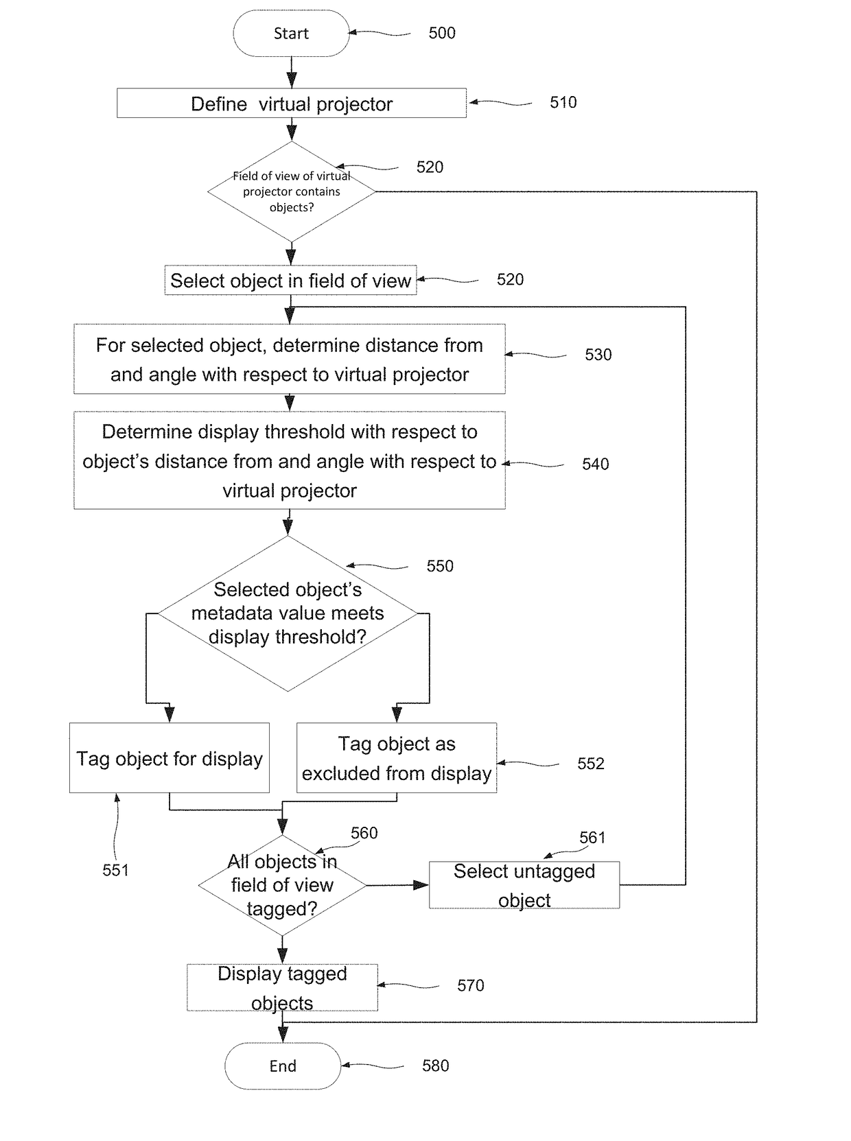
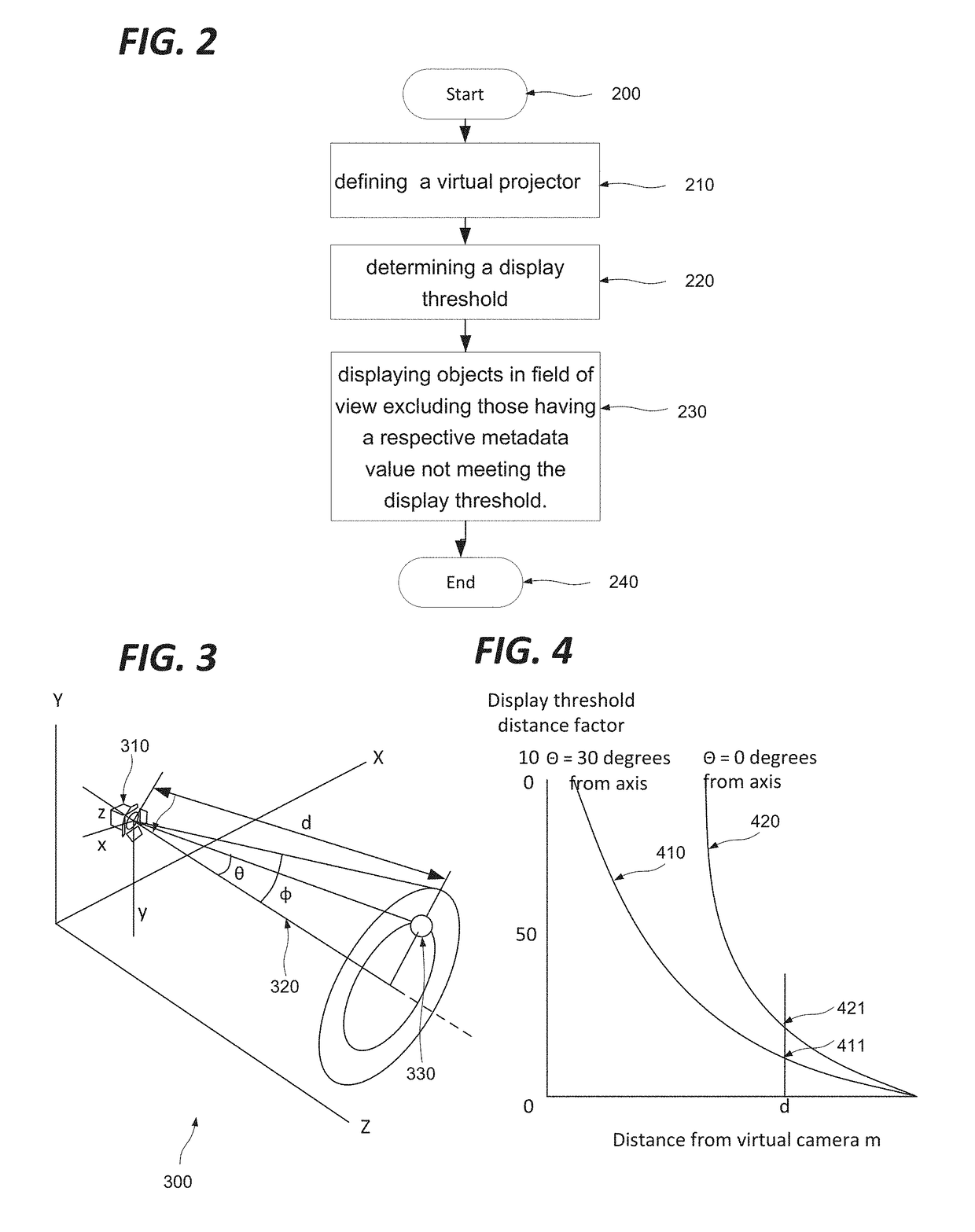
[0055]FIG. 2 shows a method according to an embodiment. More particularly, FIG. 2 shows steps of a method of displaying objects having a predefined spatial relationship in a three dimensional (3D) computer generated environment such as that described above with regard to FIG. 2.

[0056]The three dimensional environment may be defined in any suitable terms, such as for example voxels, polygons (for example in polygon mesh structures), intersecting surfaces (for example NURBS surfaces or subdivision surfaces,) or equation-based representations. By way of example, certain embodiments below will be described in terms of voxel based environments; however the skilled person will appreciate that the described embodiments may be adapted to any of these other environments.

[0057]In such an environment, the objects are each associated with a respective metadata value, which can be used to define the respective visibility of said objects in representations thereof. This value may directly define ...


PUM


Abstract

To better explore a virtual 3d computer generated environment comprised of objects which may be voxels, polygons or any other construct are selectively not displayed so as to better reveal underlying objects. The objects are each associated with a metadata value which contributes to determining their visibility such as a density or opacity value. The manner of selection is somewhat analogous to the projection of a beam of light towards the objects from a virtual projector, where a display threshold is determined for each object within the field of view of said virtual projector on the basis of a display function having an inverse relation to distance from the virtual projector and further varying as a function of the angle defined by the orientation of the virtual projector and a line drawn from said virtual projector to each said object respectively. On this basis, objects having a smaller angular separation from the axis of the virtual projector, and closer to the projector, will be preferentially excluded from display.

Description

FIELD OF THE INVENTION[0001]The present invention relates to the assisted exploration of computer generated virtual environments, and in particular to managing the difficulties associated with densely populated environments.BACKGROUND OF THE INVENTION[0002]Volumetric datasets are found in many fields, such as engineering, material sciences, medical imaging, astrophysics. The exploration of volumetric datasets is not trivial, often requiring extensive knowledge and is usually heavily impacted by the specific needs of users. In most airports for example, security agents deal with such data exploration in the context of baggage inspections. X-ray and tomography are two commonly used fluoroscopic scanning systems. X-ray systems provide a flattened 2D luggage scan while tomography systems produce transversal scans, also called slices. Thanks to data processing techniques such as the Radon transform, these systems can produce a full 3D scan, comprising a set of voxels with corresponding d...

Claims


Application Information

Patent Timeline
Patent Type & Authority Applications(United States)
IPC IPC(8): G06T19/20G06T15/08G06T15/20
CPCG06T19/20G06T2219/2016G06T15/205G06T15/08G06F3/1415
Inventor HURTER, CHRISTOPHETRAORE SOMPAGNIMDI, MICHAEL
Owner FRENCH CIVIL AVIATION UNIVERSITY
Why Eureka
Try Eureka