
Payload deployment system

a payload and deployment system technology, applied in the field of robotic devices, can solve the problems of insufficient satisfaction of conventional methods for deploying payloads from robotic or unmanned systems, inability to reliably and inability to accurately detect the presence of payloads, etc., to achieve selective electrical energizing the heating element

Active Publication Date: 2017-11-09
HARRIS CORP
View PDF2 Cites 0 Cited by
  • Summary
  • Abstract
  • Description
  • Claims
  • Application Information

AI Technical Summary

Benefits of technology

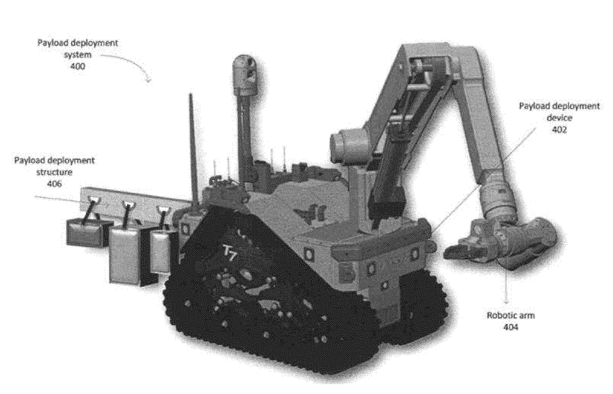
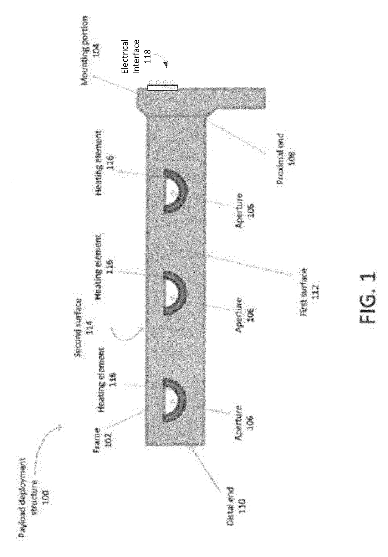
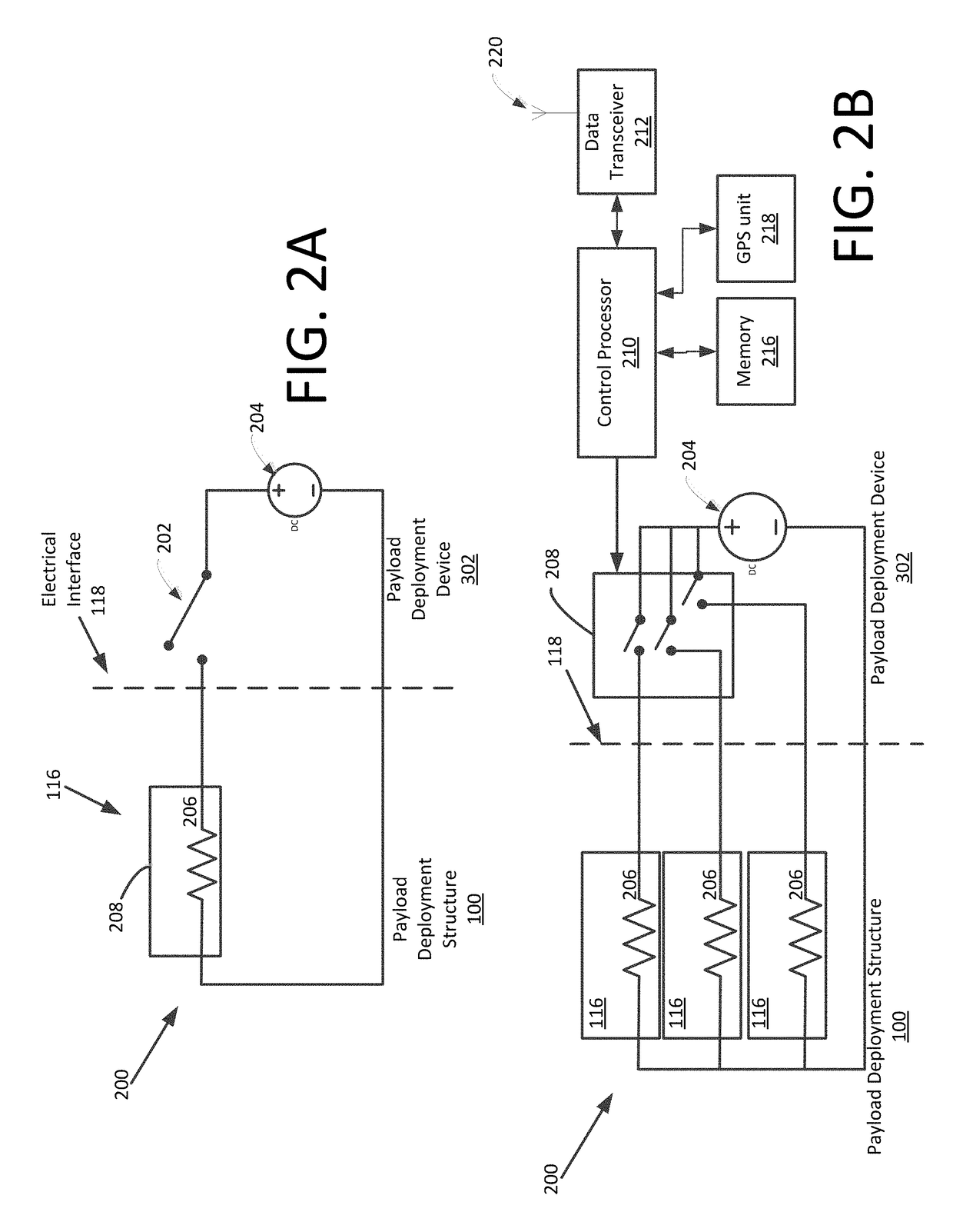
This patent describes a payloads deployment system, consisting of a device and structure. The structure has a frame with a mounting portion to connect to a robotic vehicle and a body with aperture that has a heating element. The heating element can be selectively energized. This allows for controlled deployment of payloads from the robotic vehicle. The technical effect is a safer and reliable system for deploying payloads in a controlled and efficient manner.

Problems solved by technology

However, this convention method of manual deployment is often not cost effective and can place the person deploying the payloads in harm's way.
Conventional methods for deploying payloads from a robotic or unmanned system are not entirely satisfactory.
A grasping device associated with a robotic arm could be used for this purpose but this limits the availability of the arm for other purposes.
Also, since a robotic arm associated with a UAV will typically have only a single grasping device, the number of payload items which can be carried is somewhat limited.
Conventional mechanical release mechanisms can be used in deploying payloads but such systems can be costly and complicated.
The relative complexity of such systems can also make them more prone to failure and can require maintenance to keep them in satisfactory operating condition.
Under adverse weather conditions involving rain, snow and ice, such systems may not operate consistently and reliably.
Finally, conventional mechanical payload carriage and release systems can also involve the addition of unnecessary amounts of weight or mass to the unmanned system.

Method used


Image

  • Payload deployment system
  • Payload deployment system
  • Payload deployment system

Examples


Embodiment Construction

[0012]This disclosure is not limited to the particular systems, methodologies or protocols described, as these may vary. The terminology used in this description is for the purpose of describing the particular versions or embodiments only, and is not intended to limit the scope.

[0013]As used in this document, the singular forms “a,”“an,” and “the” include plural reference unless the context clearly dictates otherwise. Unless defined otherwise, all technical and scientific terms used herein have the same meanings as commonly understood by one of ordinary skill in the art. All publications mentioned in this document are incorporated by reference. All sizes recited in this document are by way of example only, and the invention is not limited to structures having the specific sizes or dimensions recited below. As used herein, the term “comprising” means “including, but not limited to.”

[0014]The invention is described with reference to the attached figures. The figures are not drawn to s...


PUM


Abstract

Payload deployment system (400) comprises a payload deployment device (402) and a payload deployment structure (406) comprising a frame (102) having a first end, a second end, and a body extending from the first end toward the second end. The frame includes an aperture (106) located along a length of the body, wherein the aperture extends from a first surface of the frame to a second surface of the frame. A heating element (116) is located along a portion of an edge of the aperture, wherein the heating element is configured to be selectively electrically energized. The frame further includes a mounting portion (104) wherein the payload deployment structure is connected to the payload deployment device via the mounting portion.

Description

BACKGROUND OF THE INVENTIONStatement of the Technical Field[0001]The inventive arrangements relate to robotic devices, and more particularly to robotic devices which are capable of deploying payload items.Description of the Related Art[0002]There is a growing need to deploy a variety of payloads, such as, for example, cameras, communication sensor and parcels, from robotic devices and unmanned systems. It is common for payload deployment to be performed manually by human personnel and without the use of unmanned system robotics. However, this convention method of manual deployment is often not cost effective and can place the person deploying the payloads in harm's way. For this reason, the use of robotic devices and unmanned systems for the deployment of payloads can be highly desirable. Still, such arrangements require some apparatus to facilitate carriage of the payload and eventual deployment when the payload is delivered to a desired location.[0003]Conventional methods for depl...

Claims


Application Information

Patent Timeline
IPC IPC(8): B26F3/08B26F3/02
CPCB26F3/08B64C2201/128B26F3/02B64U2101/60B60P3/007B64D1/12F41H7/005B60P3/005
Inventor SUMMER, MATTHEW D.BOSSCHER, PAUL M.
Owner HARRIS CORP
Learn More