
In-ground receptacle and installation thereof

a technology of in-ground receptacles and installation parts, which is applied in the field of in-ground receptacles and installation of such devices, can solve the problems of long removal time and logistical challenges, and achieve the effect of increasing girth

Active Publication Date: 2017-11-09
EARTHBIN
View PDF21 Cites 0 Cited by
  • Summary
  • Abstract
  • Description
  • Claims
  • Application Information

AI Technical Summary

Benefits of technology

The invention is a ground well liner that can be stacked with other liners of the same type. It is made of a polymeric material and is water-tight. The liner has a bottom member and a peripheral wall extending thereabout and standing upwardly therefrom. The peripheral wall has an upper region and a lower region. The lower region has an array of anchor seats defined therein. The liner can be used in combination with anchor fittings mounted in the anchor seats. The liner has a doubled lowermost margin and the seats have outwardly extending prongs that are embedded in concrete above and below. The technical effects of the invention include increased girth upwardly, stackable with other liners, and a reinforced lower region for better stability.

Problems solved by technology

Waste removal has long, presented logistical challenges.

Method used


Image

  • In-ground receptacle and installation thereof
  • In-ground receptacle and installation thereof
  • In-ground receptacle and installation thereof

Examples


Embodiment Construction

[0030]The description that follows, and the embodiments described therein, are provided by way of illustration of an example, or examples, of particular embodiments incorporating one or more of the principles, aspects and features of the present invention. These examples are provided for the purposes of explanation, and not of limitation, of those principles and of the invention. In the description, like parts are marked throughout the specification and the drawings with the same respective reference numerals. The drawings may be understood to be to scale and in proportion unless otherwise noted. The wording used herein is intended to include both singular and plural where such would be understood, and to include synonyms or analogous terminology to the terminology used, and to include equivalents thereof in English or in any language into which this specification many be translated, without being limited to specific words or phrases.

[0031]The scope of the invention herein is define...


PUM


Abstract

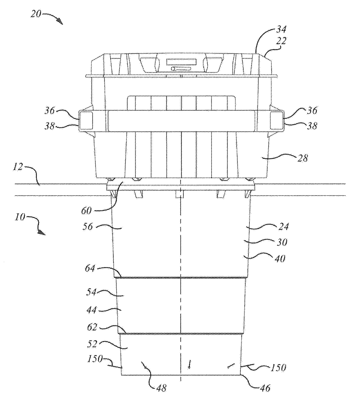
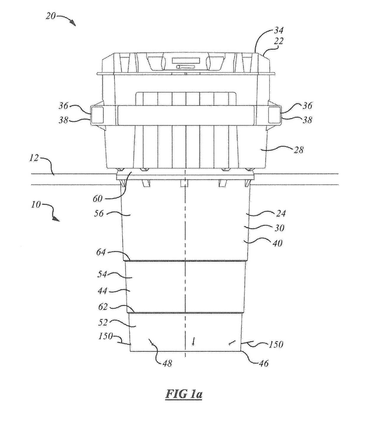
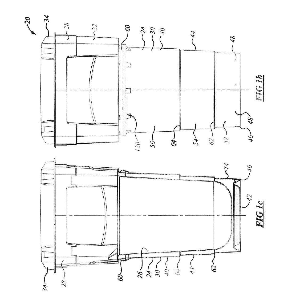
An in-ground apparatus includes a receptacle and a liner into which the receptacle can be placed and removed. The liner may be a molded plastic liner having a tapering body to permit stacking. The lower margin includes a set of seats for anchor fittings in the form of re-bar prongs that, when installed, extend radially outwardly from the liner. The seats, and hence the prongs, are located upwardly of the bottom edge of the liner so that they are embedded above and below when concrete is poured around the bottom of the liner. The bottom edge of the liner is folded upwardly and inwardly to form a V-shaped channel. The seats for the anchor fittings extend across the channel. The seats may include a cylindrical wall sealed from the inside of the liner. The liner may have intermediate stiffening ribs between bottom and top. The top of the liner may have a seat for the receptacle, and an external concrete break.

Description

FIELD OF THE INVENTION[0001]This invention relates to the field of in-ground installations.BACKGROUND OF THE INVENTION[0002]Waste removal has long, presented logistical challenges. In some locations, particularly those at fast-food restaurants, or in urban areas, a large waste receptacle is employed. Typically, the waste receptacle is filled by persons depositing waste over a period of time, and is emptied once or twice a week by a truck. The truck typically has a lifting device, such as lifting forks, and may have a compacting ram. Large receptacles, such as dumpsters, are frequently used for this purpose.[0003]Whereas dumpsters tend to sit on the ground, it is also known to provide refuse collection apparatus that is partially buried, or sits in a well in which a significant portion of the apparatus is located below grade. An apparatus that sits partially below wade may tend to be less accessible to animals, may tend to be less easily overturned, may tend to be more resistant to f...

Claims


Application Information

Patent Timeline
Patent Type & Authority Applications(United States)
IPC IPC(8): B65F1/14
CPCB65F1/1447B65F1/122
Inventor HALLMAN, DAVID
Owner EARTHBIN
Learn More