Valve for inflatable apparatuses

a valve and inflatable technology, applied in the field of valves for inflatable apparatuses, can solve the problems of tedious and cumbersome deflation process, and achieve the effect of convenient deflation

Inactive Publication Date: 2017-11-16
OASE OUTDOORS
View PDF10 Cites 3 Cited by
  • Summary
  • Abstract
  • Description
  • Claims
  • Application Information

AI Technical Summary

Benefits of technology

[0003]It is an object of the present invention to provide an inflatable apparatus that is easy to deflate.
[0010]In one or more embodiments, the first opening of the housing is configured and dimensioned as a mouthpiece. This is an advantage when a user wants to inflate the inflatable apparatus by blowing air into its lumen.
[0011]In one or more embodiments, the housing extends laterally into two oppositely directed plates or sheets. This is to allow for a better fastening of the housing / valve to the inflatable apparatus, more specifically to the air impervious material having a fabric exterior.
[0015]In one or more embodiments, the cover plate is made from a non-porous material. This is to avoid that air may leak through the material.

Problems solved by technology

A general problem with self-inflating mats is that the cell foam core forces air into the mat at the same time the user is trying to deflate it, which makes the deflation process tedious and cumbersome.

Method used


Image

  • Valve for inflatable apparatuses
  • Valve for inflatable apparatuses
  • Valve for inflatable apparatuses

Examples


Embodiment Construction

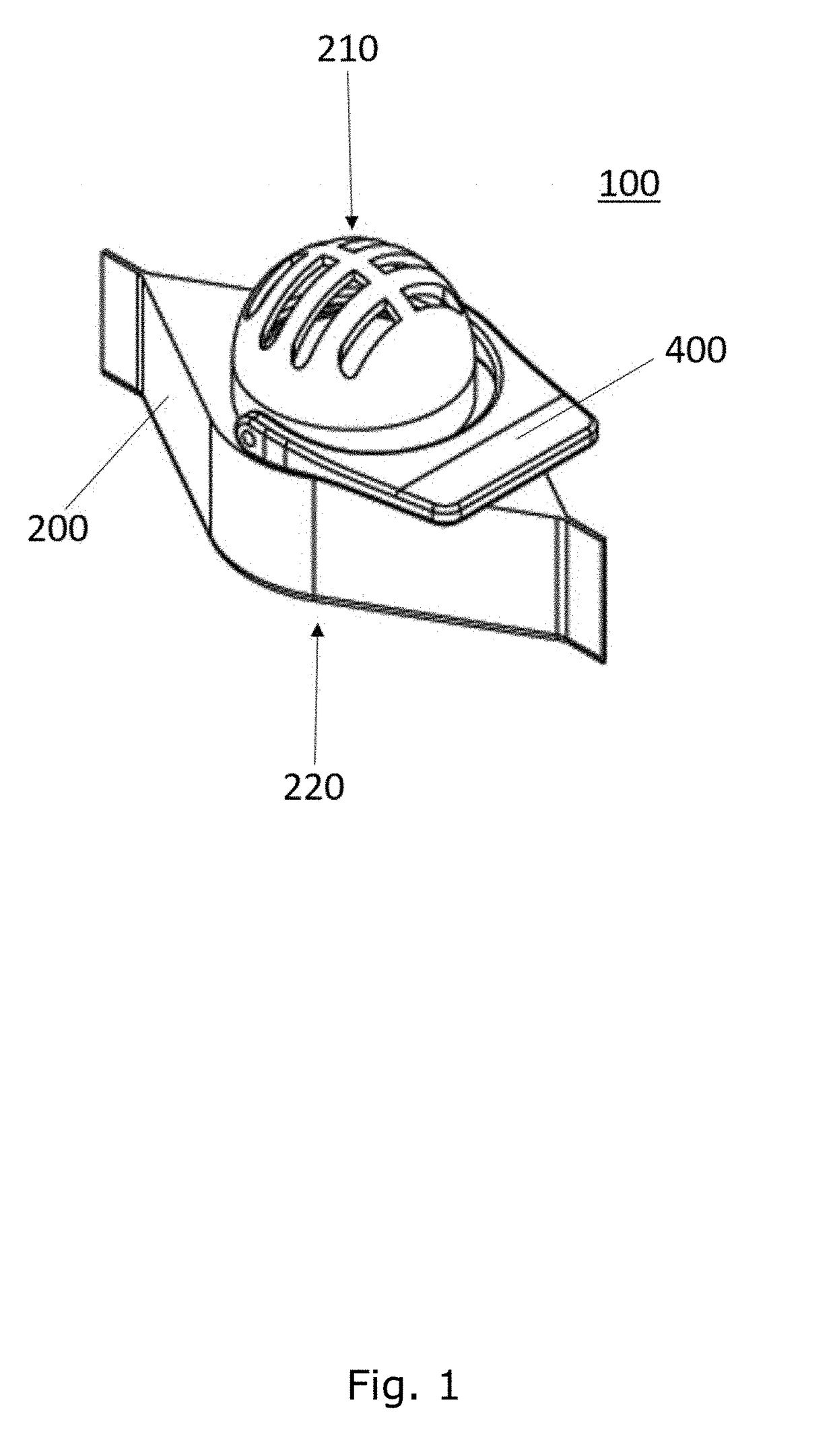
[0027]FIG. 1 shows a perspective view of valve 100 for inflatable apparatuses in accordance with various embodiments of the invention. The valve 100 comprises a housing 200, a sealing disc 300 (FIG. 2) and a handle 400. The handle 400 is coupled to the sealing disc 300, and is adapted for rotating the sealing disc 300 within the housing 200 (FIGS. 2-5).

[0028]The housing 200 comprises a first opening 210 and a second opening 220, and is adapted for being mounted to an inflatable apparatus such that the second opening faces the lumen of the inflatable apparatus into which it is mounted (not shown). The first opening faces the surrounding atmosphere.

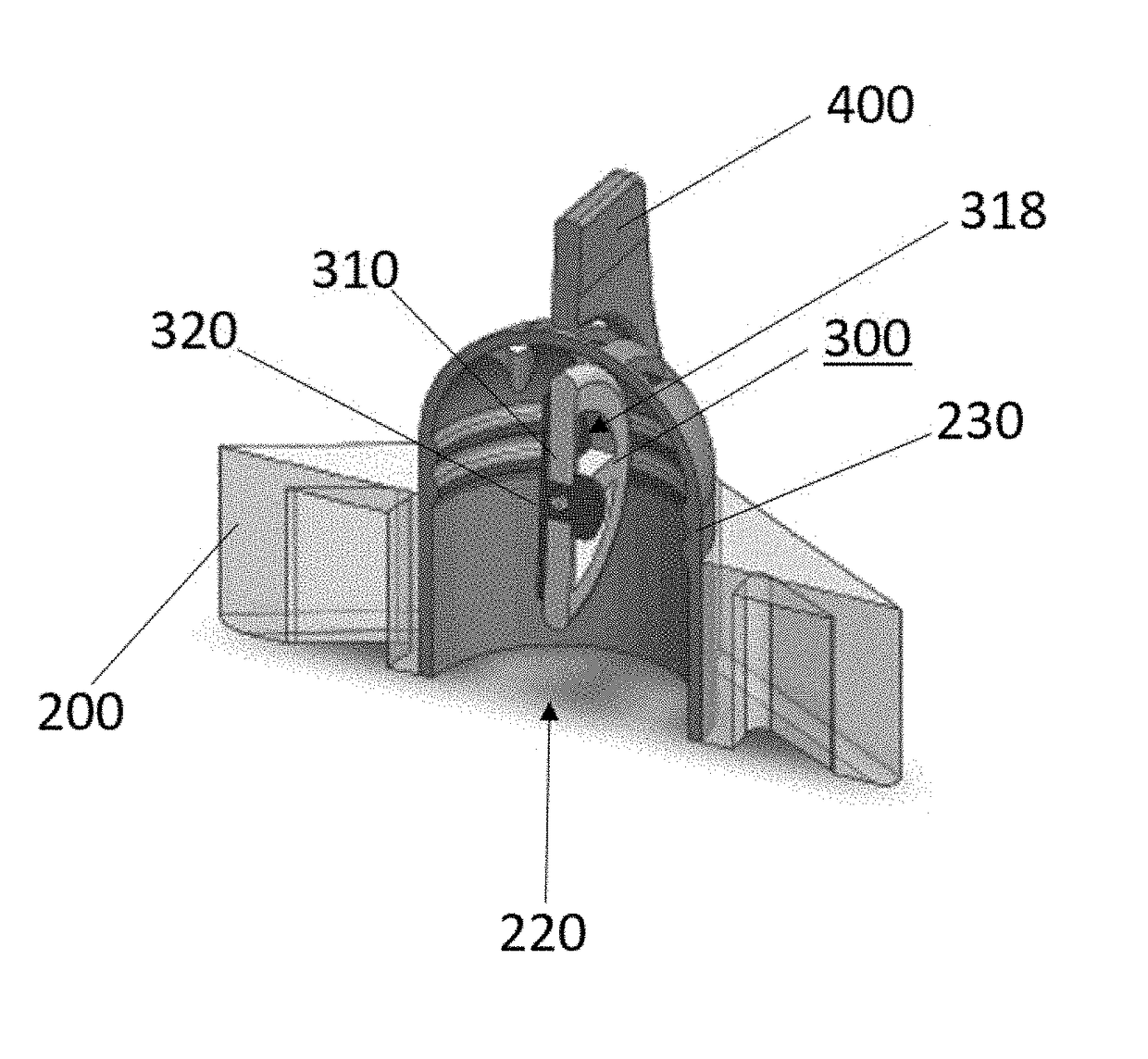
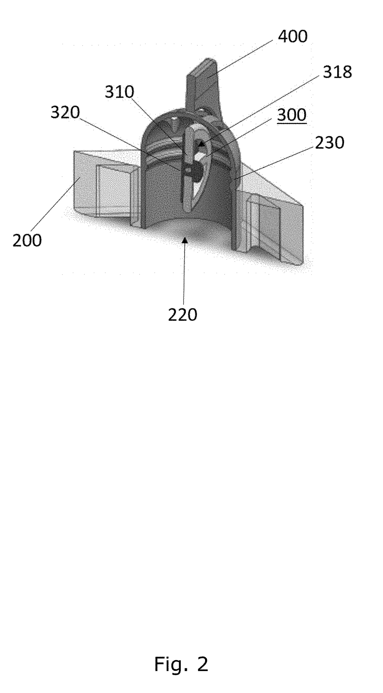
[0029]FIG. 2 shows a cross-sectional view of a valve 100 in accordance with various embodiments of the invention, where the body member 310 of the sealing disc 300 is in a released position from the inner surface side of the housing 200. Two perforation (holes / channels) 318 are shown. In this position, air may pass relatively unhindered thr...


PUM


Abstract

The present invention relates to a valve for inflatable apparatuses. The valve comprises a housing, a sealing disc and a handle. The handle is coupled to the sealing disc, and is adapted for rotating the sealing disc within the housing.

Description

TECHNICAL FIELD OF THE INVENTION[0001]The present invention relates to valves for inflatable apparatuses, and specifically for self-inflating apparatuses, such as mats, mattresses, and pillows.BACKGROUND OF THE INVENTION[0002]Camp mats are commonly used in camping and other outdoor activities, as well as indoor activities, to provide added comfort when sleeping in a tent, on the ground or on a floor or other hard surface. Self-inflating mats comprises an open cell foam core covered with an air impervious material having a fabric exterior, and a valve for inflating and deflating. A general problem with self-inflating mats is that the cell foam core forces air into the mat at the same time the user is trying to deflate it, which makes the deflation process tedious and cumbersome.SUMMARY OF THE INVENTION[0003]It is an object of the present invention to provide an inflatable apparatus that is easy to deflate.[0004]One aspect relates to a valve for inflatable apparatuses comprising:[0005...

Claims


Application Information

Patent Timeline
Patent Type & Authority Applications(United States)
IPC IPC(8): F16K15/20F16K15/14A47C27/08A47G9/10F16K31/60F16K15/18
CPCF16K15/202F16K15/148F16K15/185F16K31/602A47C27/084A47G9/1027F16K1/22F16K1/36F16K1/222F16K1/223F16K15/207F16K15/1825Y10T137/3631Y10T137/5153Y10T137/784
Inventor ARENS, HENRIK
Owner OASE OUTDOORS
Why Eureka
Try Eureka