Inflatable antenna system

a technology of inflatable antennas and antenna frames, which is applied in the direction of antennas, antenna details, and movable body antenna adaptation, etc., can solve the problems of requiring additional tools for erection, and requiring a large amount of space for transpor

Inactive Publication Date: 2007-01-11
AVALONRF
View PDF8 Cites 2 Cited by
  • Summary
  • Abstract
  • Description
  • Claims
  • Application Information

AI Technical Summary

Benefits of technology

[0008] The principle advantage of this invention is to create an antenna printed or wired on an inflatable cylinder or cone made of flexible radio frequency grade material for use in highly mobile military and public safety applications.

Problems solved by technology

Additionally, the necessity for a rigid structure requires a good deal of space for transport, weight for transport, and additional time for set up.
This erection of a rigid frame would be time consuming, require additional tools for erection and would also prove to be cumbersome.
The described antenna appears to be bulky, difficult to transport, erect and dismantle, and generally looks awkward to deploy.

Method used


Image

  • Inflatable antenna system
  • Inflatable antenna system
  • Inflatable antenna system

Examples


Embodiment Construction

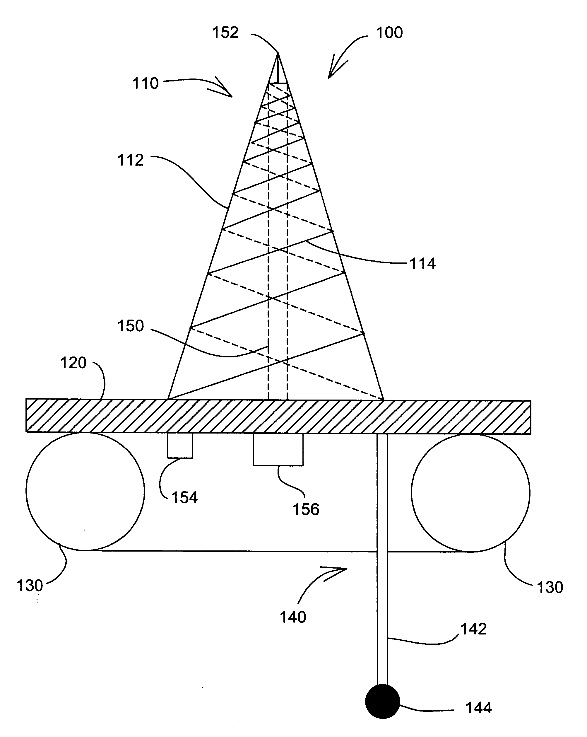
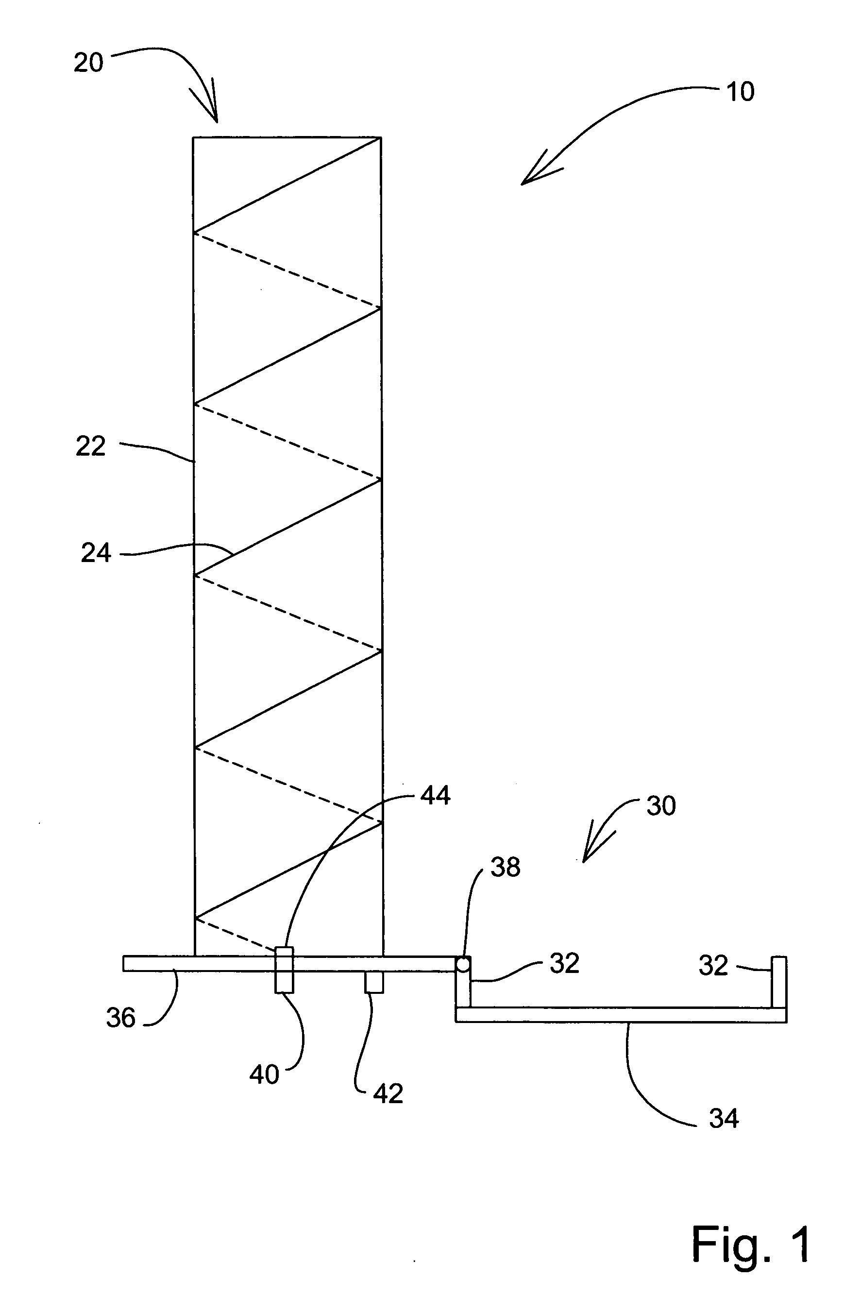
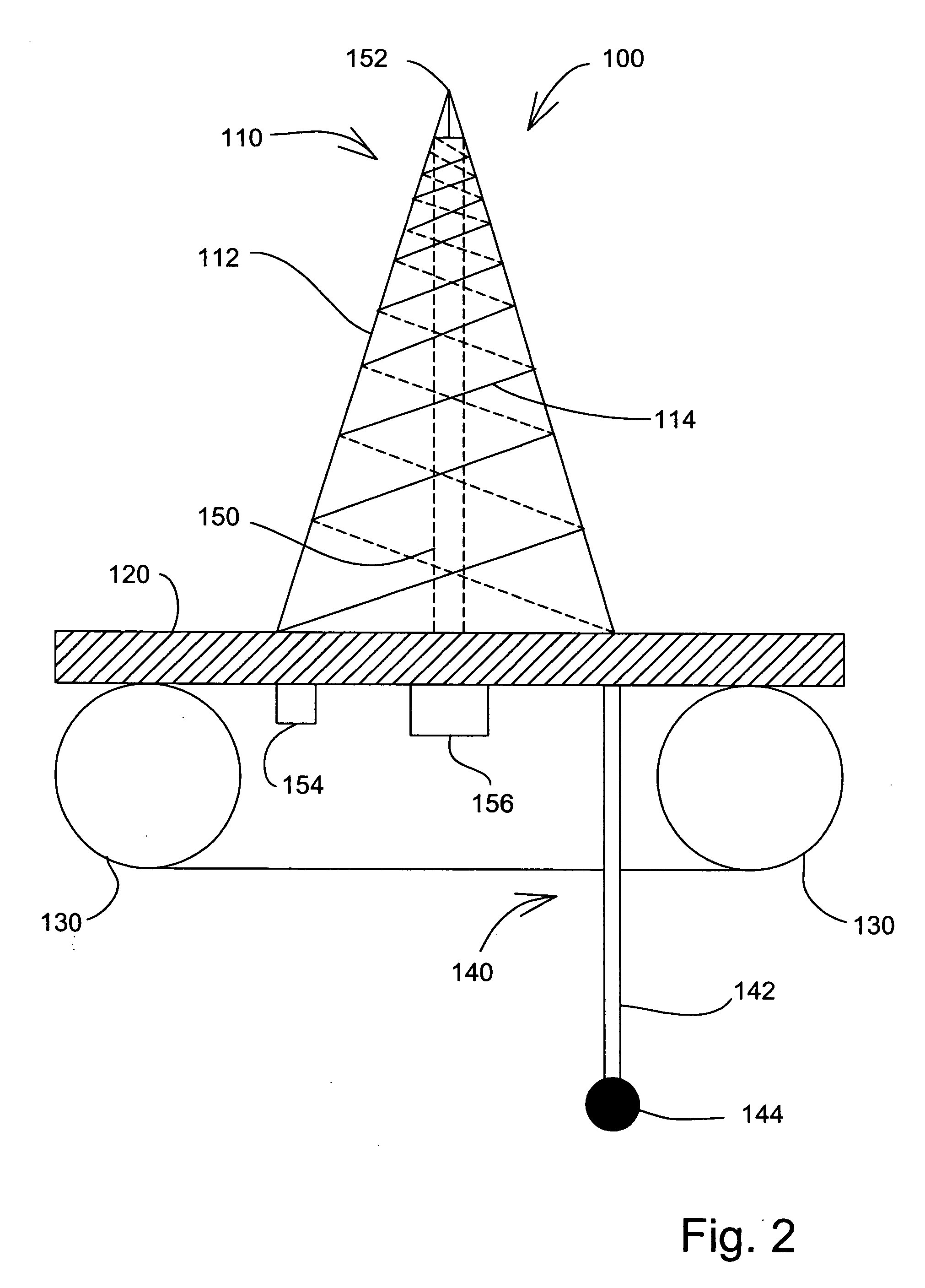
[0024] Referring now to the drawings, wherein similar parts are identified by like reference numerals, there is seen in FIG. 1 a side view of the preferred embodiment of the inflatable antenna system 10. Inflatable antenna system 10 includes a wide band, narrow viewing angle, helical inflatable antenna 20 and a protective enclosure 30. Inflatable antenna 20 includes an inflatable member 22 and a plurality of conductors 24. Inflatable member 22 can be comprised of highly flexible microwave quality composite material, such as Kapton®. Although inflatable member 22 can take the form of many shapes, the preferred shape of inflatable member 22 is cylindrical. Conductors 24 are antenna elements that can be integrated into inflatable member 22 by methods including, but not limited to, printing, gluing, or weaving, to meet antenna topology requirements and / or provide high quality (Q) at the spectrum of operation of the inflatable antenna 20.

[0025] Protective enclosure 30 is rectangular in ...


PUM


Abstract

The present invention involves an inflatable antenna system including an inflatable antenna and a mounting plate. The inflatable antenna includes an inflatable cone or cylinder and a plurality of conductors integrated therein. The mounting plate can be incorporated into a protective enclosure that holds and protects the inflatable antenna during transport, supports it during use, and provides a means for mounting it to a mast. The mounting plate serves as a mounting surface for the inflatable antenna, a radio frequency (RF) connector, an air intake valve, and an impedance matching network. Selected surfaces of the protective enclosure can be coated with conductive materials. An air intake valve allows for inflation and deflation of the inflatable antenna. Inflatable support members can be used in conjunction with a stabilizing portion comprised of a vertical member and attached weight, to allow the inflatable antenna system to be deployed in water.

Description

FIELD OF THE INVENTION [0001] The present invention relates generally to inflatable antenna structures, and more particularly to an integrated conductor and inflatable cone or cylinder which may be both quickly deployed and quickly folded, providing a relatively lightweight and compact antenna for highly mobile military and public safety applications. BACKGROUND OF THE INVENTION [0002] Inflatable antennae have been described in prior art. One such inflatable antenna is described in U.S. Pat. No. 6,650,304 B2. This novel invention describes an antenna that includes an inflatable envelope, a cylindrical reflector formed on a wall of the envelope, a support frame for maintaining the cylindrical shape of the cylindrical reflector and a feed array support structure connected to the catenary support frame. While this invention incorporates a reflective coating utilizing a rigid support frame, there is no integrated antenna, thereby providing for effective relay of information to a separat...

Claims


Application Information

Patent Timeline
Patent Type & Authority Applications(United States)
IPC IPC(8): H01Q1/34
CPCH01Q1/34H01Q1/081
Inventor WEINSTEIN, ELIAHU
Owner AVALONRF
Why Eureka
Try Eureka