Semi rigid edge protection design for stent delivery system

a delivery system and rigid edge technology, applied in the field of implantable medical devices, can solve the problems of balloon bursting, embolism or vessel damage, and failure to reach the intended target, and achieve the effect of facilitating balloon inflation or deflation

Active Publication Date: 2014-08-05
BOSTON SCI SCIMED INC
View PDF33 Cites 4 Cited by
  • Summary
  • Abstract
  • Description
  • Claims
  • Application Information

AI Technical Summary

Benefits of technology

[0013]At least one of the embodiments of the inventive concept is directed to an SDS having an outer neck which extends distally into the balloon cone or distally into the balloon working region. The inventive concept also contemplates at least one embodiment directed to an SDS having a tapered outer neck. At least one embodiment encompassed by the inventive concept is directed to an SDS having one or more aperture extending through the side walls of the outer neck. In at least one embodiment these apertures facilitate the inflation or deflation of a balloon.

Problems solved by technology

Non-implantation may result from a number of causes including but not limited to lack of success in reaching the intended target lesion.
The already tracked device at this point however could have experienced flexing which can cause flaring at one or more ends of the stent.
This can result in the flared end(s) of the stent catching on portions of the body vessel upon further movement in either direction and thus cause embolization or vessel damage.

Method used


Image

  • Semi rigid edge protection design for stent delivery system
  • Semi rigid edge protection design for stent delivery system
  • Semi rigid edge protection design for stent delivery system

Examples


Embodiment Construction

[0028]The invention will next be illustrated with reference to the figures wherein the same numbers indicate similar elements in all figures. Such figures are intended to be illustrative rather than limiting and are included herewith to facilitate the explanation of the apparatus of the present invention. For the purposes of this disclosure, like reference numerals in the figures shall refer to like features unless otherwise indicated. Depicted in the figures are various aspects of the invention. Elements depicted in one figure may be combined with, or substituted for, elements depicted in another figure as desired.

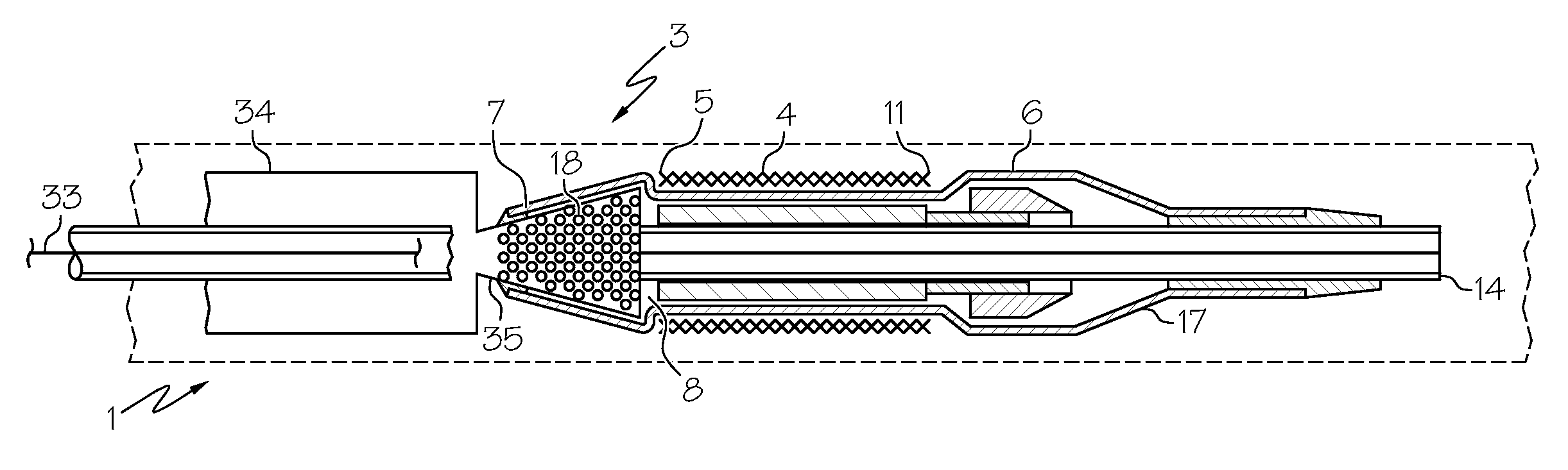
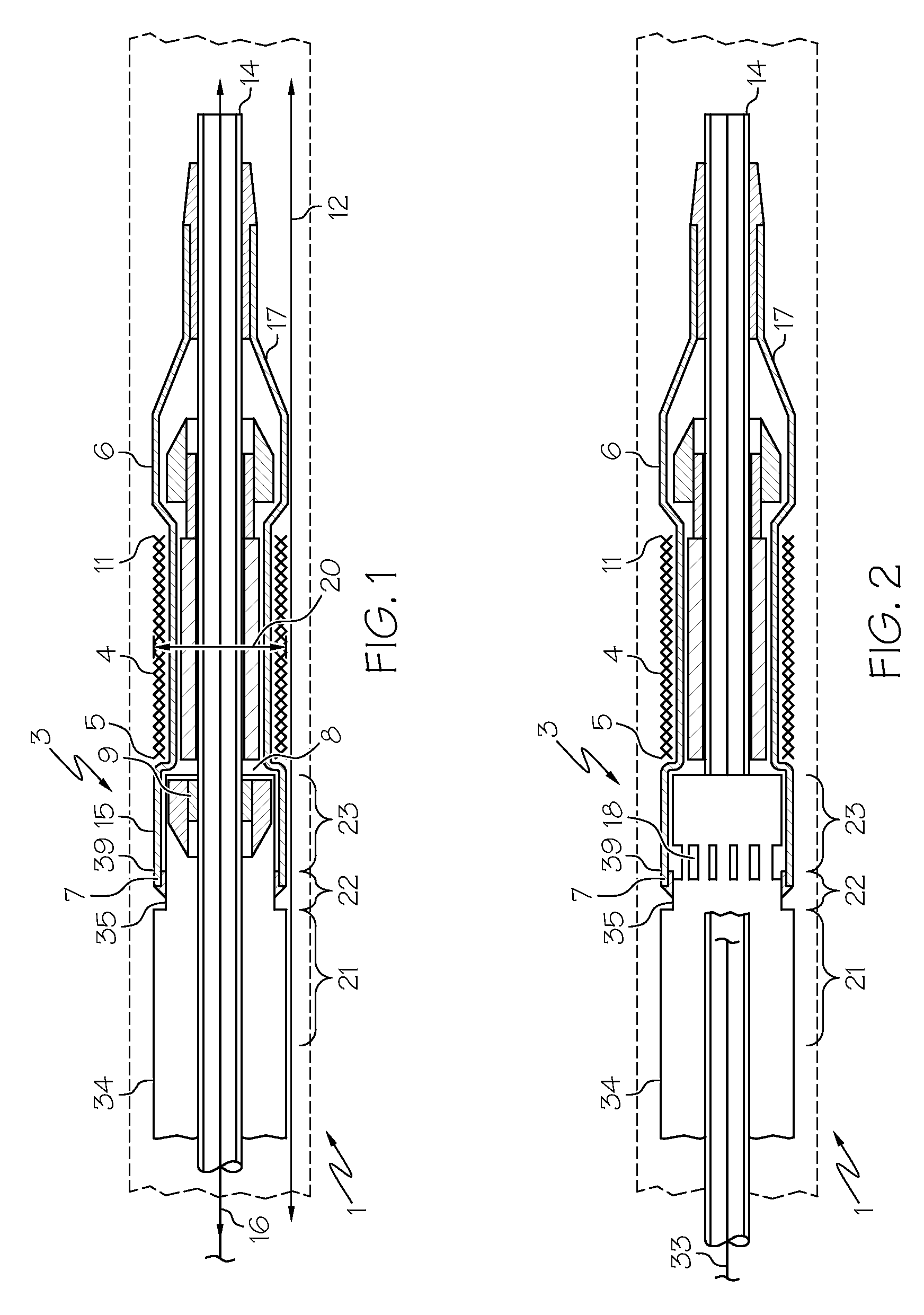
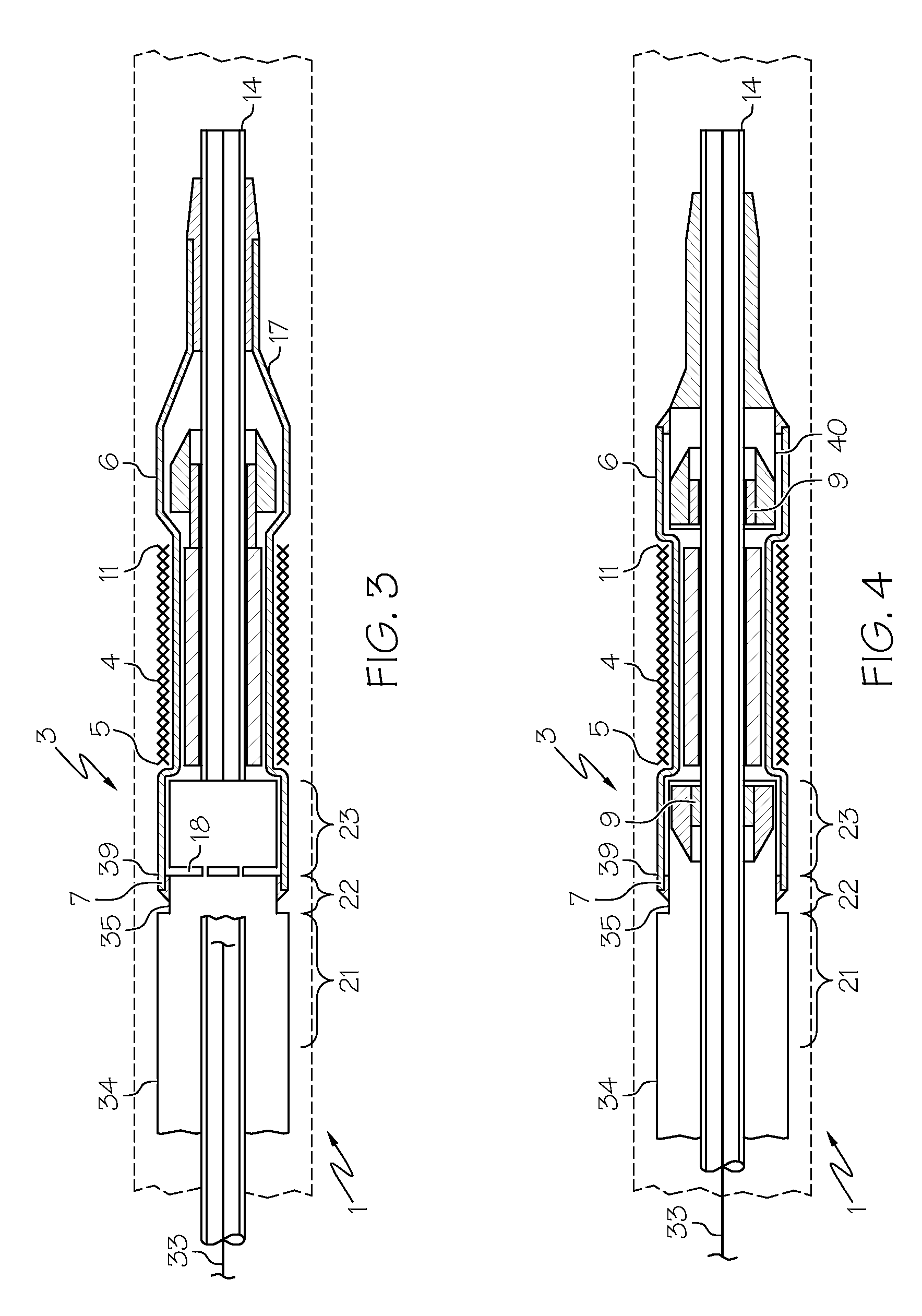
[0029]Referring now to FIG. 1 there is shown a stent delivery system (SDS) (1) in an unexpanded configuration. The SDS (1) comprises an unexpanded stent (4) crimped about a catheter or shaft (3). The stent (4) has a proximal edge (5) and a distal edge (11) and is constructed to have a tubular structure with a diameter (20). The diameter (20) has a first magnitude which pe...


PUM


Abstract

A system to deliver or remove an inflation expandable stent in a body vessel. The system avoids causing damage or embolisms to a body vessel it is traversing by restraining the edges of the stent from scraping against the walls of the body vessel. The edges are restrained by balloon folds, compressive wedging, and angled reflective resistance. In addition the device can also inflate or deflate the balloon more efficiently.

Description

CROSS-REFERENCE TO RELATED APPLICATIONS[0001]Not ApplicableSTATEMENT REGARDING FEDERALLY SPONSORED RESEARCH[0002]Not ApplicableBACKGROUND OF THE INVENTION[0003]1. Field of the Invention[0004]In some embodiments this invention relates to implantable medical devices, their manufacture, and methods of use. More particularly some embodiments of this invention relate to delivery systems for intravascular stents, such as catheter systems of all types, which are utilized in the delivery of such devices.[0005]2. Description of the Related Art[0006]A stent is a medical device introduced to a body lumen and is well known in the art. Typically, a stent is implanted in a blood vessel at the site of a stenosis or aneurysm endoluminally, i.e. by so-called “minimally invasive techniques” in which the stent in a radially reduced configuration is delivered by a stent delivery system or “SDS” to the site where it is required.[0007]In some circumstances however, a stent or other medical device which i...

Claims


Application Information

Patent Timeline
Patent Type & Authority Patents(United States)
IPC IPC(8): A61F2/06A61F2/95A61F2/958
CPCA61F2/958A61F2002/9586A61F2002/9528
Inventor ALKHATIB, YOUSEF
Owner BOSTON SCI SCIMED INC
Why Eureka
Try Eureka