
Lubricant level sensing for an actuator

a technology of actuator and lubricant, which is applied in the direction of liquid/fluent solid measurement, instruments, transportation and packaging, etc., can solve the problems of electromechanical actuator subject to substantial changes in orientation, velocity, acceleration, vibration, and damage, and reduce performance or damage.

Active Publication Date: 2017-11-23
SIKORSKY AIRCRAFT CORP
View PDF24 Cites 2 Cited by
  • Summary
  • Abstract
  • Description
  • Claims
  • Application Information

AI Technical Summary

Benefits of technology

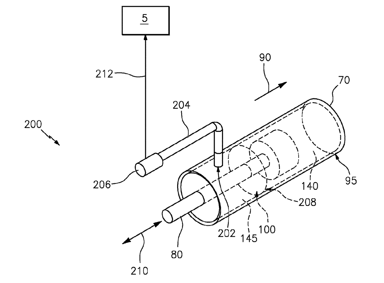
The invention relates to a lubricant level sensing system for an actuator that uses a pressure sensor and a pathway to detect changes in pressure in the actuator. This allows for the monitoring of the level of lubricant in the actuator to alert when it is low. The system includes a pressure port in the outer housing of the actuator, a pressure sensor, and a pathway that connects the pressure sensor to a free volume inside the actuator. This allows for the pressure sensor to detect changes in pressure of the free volume and determine the lubricant level in the actuator. Overall, the invention provides a way to conveniently and accurately monitor lubricant levels in actuators, which can improve their reliability and performance.

Problems solved by technology

When insufficient lubricant is retained within an electromechanical actuator, reduced performance or damage may occur.
Detection of oil level can be difficult in applications where the electromechanical actuator is mounted on a mobile structure such that the electromechanical actuator is subject to substantial changes in orientation, velocity, acceleration, and vibration.
A rotor blade control surface actuator is subject to substantial centrifugal force, as well as other forces due to blade flapping, aircraft maneuvering, aircraft speed, acceleration, environmental factors, and other factors that can result in a number of challenges to reliably detect oil level in the actuator.

Method used


Image

  • Lubricant level sensing for an actuator
  • Lubricant level sensing for an actuator
  • Lubricant level sensing for an actuator

Examples


Embodiment Construction

[0022]It is noted that various connections are set forth between elements in the following description and in the drawings (the contents of which are included in this disclosure by way of reference). It is noted that these connections in general and, unless specified otherwise, may be direct or indirect and that this specification is not intended to be limiting in this respect. In this respect, a coupling between entities may refer to either a direct or an indirect connection.

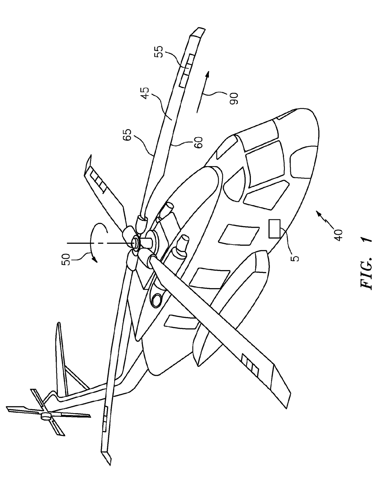
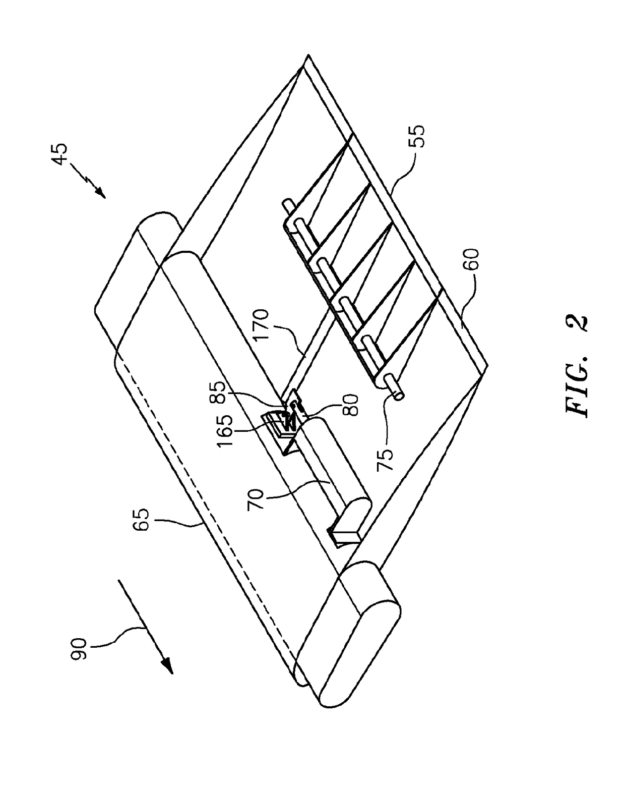
[0023]Referring to FIG. 1, a helicopter 40 is depicted having one or more rotor blades 45 configured for rotation in a rotor direction 50. Each rotor blade 45 has one or more control surfaces 55 (three shown) disposed thereon. The helicopter 40 represents one example of a system that can incorporate one or more instances of a lubricant level sensing system for an actuator as further described herein. By way of example, while shown in the context of a conventional helicopter 40, it is understood that aspects cou...


PUM


Abstract

According to one aspect, a lubricant level sensing system for an actuator is provided. The lubricant level sensing system includes a pressure port in an outer housing of the actuator, a pressure sensor, and a pathway from the pressure port to the pressure sensor. The pathway establishes fluid communication between the pressure sensor and a free volume of an internal cavity of the outer housing relative to a lubricant level in the internal cavity such that the pressure sensor detects a pressure of the free volume used to derive the lubricant level.

Description

STATEMENT REGARDING FEDERALLY SPONSORED RESEARCH OR DEVELOPMENT[0001]This invention was made with government support under contract number W911W6-11-2-0004 awarded by the United States Army. The government has certain rights in the invention.BACKGROUND OF THE INVENTION[0002]The subject matter disclosed herein relates to fluid level sensing, and in particular to lubricant level sensing for an actuator.[0003]Actuators, such as electromechanical actuators, typically require an adequate amount of lubrication. When insufficient lubricant is retained within an electromechanical actuator, reduced performance or damage may occur. Detection of oil level can be difficult in applications where the electromechanical actuator is mounted on a mobile structure such that the electromechanical actuator is subject to substantial changes in orientation, velocity, acceleration, and vibration. One example is a self-lubricated actuator for a rotor blade control surface of a helicopter, where a lubricatio...

Claims


Application Information

Patent Timeline
Patent Type & Authority Applications(United States)
IPC IPC(8): F16N29/00G01F23/16B64C27/615B64C27/72
CPCF16N29/00B64C27/72B64C27/615B64C2027/7294F16N2250/04F16N2250/18G01F23/164
Inventor MATALANIS, CLAUDE G.JONSSON, ULF J.CANNATA, JOHN D.WAKE, BRIAN E.
Owner SIKORSKY AIRCRAFT CORP
Learn More