In-Ear Utility Device Having Sensors

a technology sensors, which is applied in the field of in-ear utility devices, can solve the problems of limited technological abilities, bulky and uncomfortable ear pieces, and conventional limitations in the prospect of exploring new form factors for ear pieces

Inactive Publication Date: 2017-11-30
SMARTEAR INC
View PDF18 Cites 26 Cited by
  • Summary
  • Abstract
  • Description
  • Claims
  • Application Information

AI Technical Summary

Benefits of technology

[0007]Embodiments of the invention provide a wireless in-ear utility device, comprising a body having at least a portion shaped to fit into a user's ear canal. The body has a distal end configured to reside in the user's ear canal at a distance from 7 to 12 millimeters away from the user's ear drum. The wireless in-ear utility device includes an accelerometer located in the body, the accelerometer configured to determine changes in the user's head position. The wireless in-ear utility device also includes a data storage component having a driving safety application. The wireless in-ear utility device further includes a processor configured to execute the driving safety application, receive inputs from the accelerometer and determine if the user is falling asleep.
[0008]Embodiments of the invention include a method for operating a wireless in-ear utility device. The method comprises measuring changes to a user's head position by an accelerometer located in a body of the in-ear wireless device, wherein the body has at least a portion shaped to fit into a user's ear canal, the body having a distal end configured to reside in the user's ear canal at a distance from 7 to 12 millimeters away from the user's ear drum. The method additionally includes determining by the processor if the user is falling asleep by executing a driving safety application stored in a data storage component using the accelerometer data against instructions found in the driving safety application.

Problems solved by technology

However, previous ear pieces have traditionally been bulky and uncomfortable as well as being limited in their technological abilities.
Thus, the prospects for exploring new form factors for ear pieces have conventionally been limited.
Moreover, these ear pieces have conventionally been devices slaved to other devices, such as smartphones, with limited abilities to operate independently.
Similarly, the prospects for exploring new and independent uses for ear pieces have also been limited conventionally.

Method used


Image

  • In-Ear Utility Device Having Sensors
  • In-Ear Utility Device Having Sensors
  • In-Ear Utility Device Having Sensors

Examples


Embodiment Construction

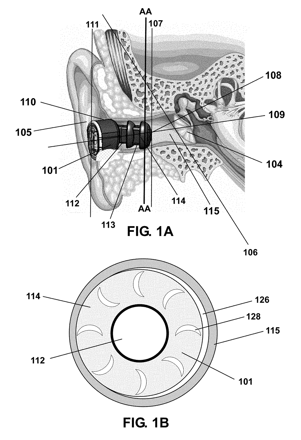
[0033]Embodiments of the invention provide a wireless in-ear utility device having a speaker placed closer to the user's eardrum than conventional sound-delivery devices but not typically as close as some medically-regulated hearing aids. Embodiments of the in-ear utility device may be used for a variety of purposes and include a variety of electronic packages, such as for use as an amplified hearing device, for use as a music player, for use as a headphone device, and for use in various health-monitoring applications.

[0034]Embodiments of the invention provide a wireless in-ear utility device configured to have a variety of electronic packages. The electronic packages may serve a variety of functions, such as a Bluetooth device, a noise cancellation device that allows the user to focus on sounds of interest, a health-monitoring device, and a fitness device, each embodiment having the sensors and electronic configuration needed to carry out its mission. Embodiments of the wireless in...


PUM


Abstract

An embodiment of the invention provides a wireless in-ear utility device that rests in the user's ear canal near the user's eardrum. The in-ear utility device may be configured in a variety of ways, including, but in no way limited to a smart in-ear utility device, a flexible personal sound amplification product, a personal music player, a “walkie-talkie” and the like.

Description

CROSS-REFERENCE TO RELATED APPLICATIONS[0001]The present application is related to co-filed U.S. patent application Ser. No. ______ entitled “In-Ear Utility Device Having Tap Detector,” (Attorney Docket Number SmartEar-002US); U.S. patent application Ser. No. ______ entitled “In-Ear Utility Device Having Dual Microphones,” (Attorney Docket Number SmartEar-006US); U.S. patent application Ser. No. ______ entitled “In-Ear Utility Device Having Sensors,” (Attorney Docket Number SmartEar-007US); U.S. patent application Ser. No. ______ entitled “In-Ear Utility Device Having A Humidity Sensor,” (Attorney Docket Number SmartEar-008US); U.S. patent application Ser. No. ______ entitled “In-Ear Utility Device Having Information Sharing,” (Attorney Docket Number SmartEar-009US), and U.S. patent application Ser. No. ______ entitled “In-Ear Utility Device Having Voice Recognition” (Attorney Docket Number SmartEar-010US), which are assigned to the assignee of the present application. These related...

Claims


Application Information

Patent Timeline
Patent Type & Authority Applications(United States)
IPC IPC(8): H04R1/10H04R29/00A61B5/02A61B5/00A61B5/0404A61B5/0205A61B5/0476A61B5/021A61B5/024A61B5/08A61B5/083A61B5/11A61B5/1455A61B5/332
CPCH04R1/1016A61B2562/029A61B5/02055A61B5/02028A61B5/0404A61B5/0476A61B5/6817H04R2420/07H04R2201/103H04R1/1091A61B5/021A61B5/02405A61B5/02438A61B5/0533A61B5/0816A61B5/0833A61B5/11A61B5/14552A61B2560/0252A61B2562/0219A61B2562/0223A61B2562/0247H04R29/001H04R1/1041H04R3/005H04R25/02H04R25/356H04R25/65H04R25/652H04R25/656H04R2201/403H04R2410/05H04R2460/03A61B5/6815A61B5/1118A61B5/332A61B5/369
Inventor MASAKI, KINUKOGARDNER, DEANVALENZUELA, VICTOR
Owner SMARTEAR INC
Why Eureka
Try Eureka