Deposition print head

a printing head and print head technology, applied in the direction of coil arrangement, induction heating, induction heating apparatus, etc., can solve the problems of degeneration of material, delay in operation of the printing head, and fouling of the deposition printer comprising the deposition print head, so as to adapt to different filament materials, the effect of adaptability

Inactive Publication Date: 2017-12-07
BOND HIGH PERFORMANCE 3D TECH BV
View PDF4 Cites 9 Cited by
  • Summary
  • Abstract
  • Description
  • Claims
  • Application Information

AI Technical Summary

Benefits of technology

[0037]In a further embodiment according to the invention, the method further comprises controlling a filament channel temperature. This allows accurate implementation of te...

Problems solved by technology

A problem with such a deposition print head is that the heating element body needs to be maintained at a suitable temperature so that the depositing material obtains the right consistency.
This causes undesired oozing of molten filament material and thereby fouling a deposition printer comprising the deposition print head.
Furthermore continuous heating of filament material can cause material degeneration.
Moreover, intermittent operation of such a heater would cause...

Method used


Image

  • Deposition print head
  • Deposition print head
  • Deposition print head

Examples


Embodiment Construction

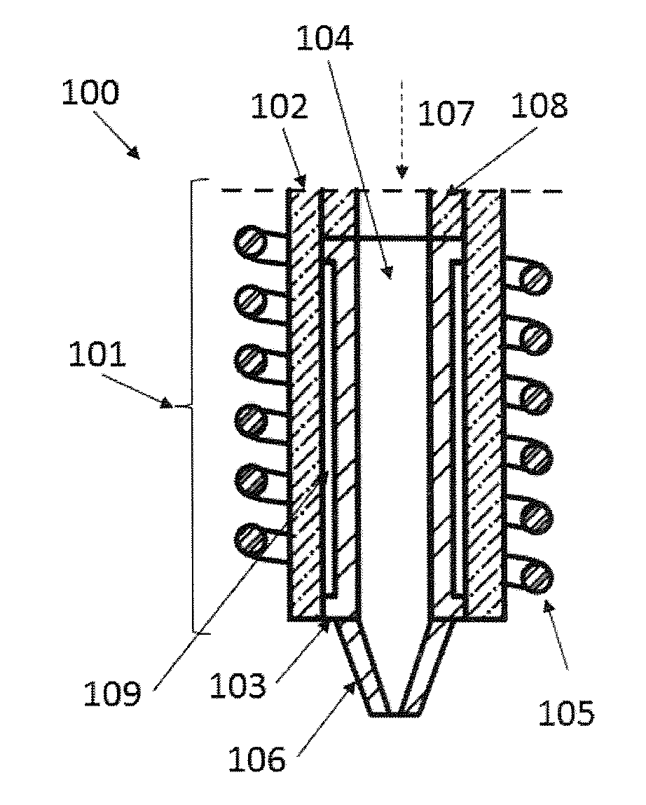
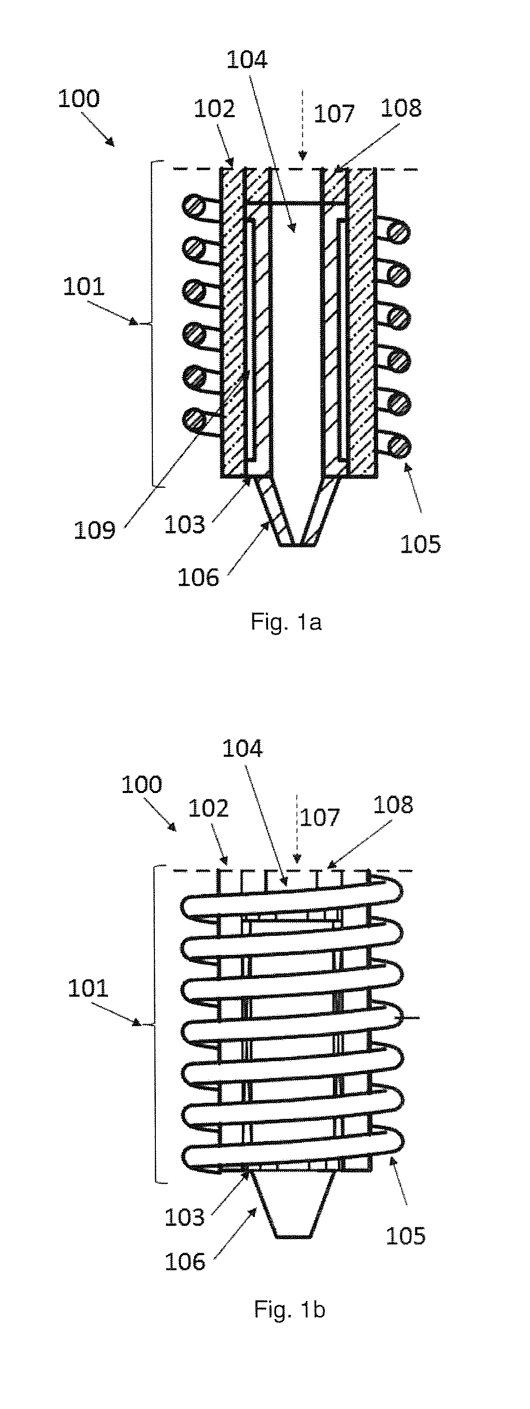
[0053]FIG. 1a shows a cross section of a deposition print head 100 having a sleeve 102, a susceptive element 103, an exciter 105 and a nozzle 106. The susceptive element 103 is arranged inside the sleeve 102. The susceptive element 103 has a tubular shape leaving a channel 104 for allowing feed through of thermoplastic filament. The exciter 105 is arranged around the susceptive element 103. The nozzle 106 can preferably be attached to the susceptive element 103, but can also be attached to the sleeve 102. The exciter 105 is connectable to an energy source such as an electric power supply, and when supplied it generates a field compatible with the susceptive element 103.

[0054]The exciter 105 can be an induction coil combined with a ferromagnetic tubular element as susceptive element 103. Ferromagnetic materials for the susceptive element 103 include iron, iron alloys. Also materials with low conductivity can be used such as steel, carbon, tin, tungsten, which cause heating up by mean...


PUM

PropertyMeasurementUnit
Temperatureaaaaaaaaaa
Poweraaaaaaaaaa
Magnetic fieldaaaaaaaaaa

Abstract

A deposition print head including a non-susceptive or low susceptive sleeve, a susceptive element having a filament channel, the susceptive element arranged inside the sleeve, wherein the susceptive element is susceptive for at least one of a magnetic field and an electrical field, wherein the filament channel is for feeding a thermoplastic filament in a feed direction. The deposition print head further includes an exciter arranged around the susceptive element, wherein the exciter is arranged for generating a field compatible with the susceptivity of the susceptive element, and a nozzle attached to one end of the susceptive element.

Description

FIELD OF THE INVENTION[0001]The invention relates to a deposition print head, a deposition print head assembly, a deposition printer and a method of controlling the deposition print head.BACKGROUND OF THE INVENTION[0002]Deposition print heads are known in printers for depositing fluid material on a solid surface. A well-known example is a deposition print head in a three dimensional printer which deposits a molten material to be deposited on a solidified body of the same or a similar material. While controlling the position of the deposition print head in space, the deposition print head can for example be used for creating three dimensional objects.[0003]Deposition print heads known in the art can comprise a heating element, a feed connected to the heating element for the material to deposit, such as plastic material, and a nozzle connected to the heating element. The heating element can comprise a heat source and a heater body and a filament channel through the heater body from th...

Claims


Application Information

Patent Timeline
IPC IPC(8): B29C64/209B29C35/08H05B6/14B29C64/227H05B6/10H05B6/44
CPCB29C64/209B29C35/0805H05B6/14H05B6/109B29C64/227H05B6/44B29C2035/0816B29C2035/0811H05B6/108
Inventor BRUGGEMAN, THOMAS JONATHANBRUGGEMAN, ADRIANUS
Owner BOND HIGH PERFORMANCE 3D TECH BV
Why Eureka
Try Eureka