Supercharge Your Innovation With Domain-Expert AI Agents!

Gas generator

a generator and gas technology, applied in the direction of vehicle components, pedestrian/occupant safety arrangements, vehicular safety arrangements, etc., can solve the problem of airbag damag

Active Publication Date: 2017-12-07
DAICEL CHEM IND LTD
View PDF0 Cites 3 Cited by
  • Summary
  • Abstract
  • Description
  • Claims
  • Application Information

AI Technical Summary

Benefits of technology

The present invention provides a gas generator with a cylindrical housing and a diffuser portion. The gas generator includes a cylindrical flow path forming member with a partition wall that separates a first chamber and a second chamber. The first chamber is filled with a gas generating agent and the second chamber acts as a gas discharge path. The gas generator also includes a plurality of communication holes and an annular filter for collecting combustion residue. The gas generator can generate a continuous gas flow for a long time period. The technical effects of the present invention include improved gas generation efficiency, reduced combustion residue, and improved gas purity.

Problems solved by technology

If such a combustion residue is directly discharged from the gas generator and enters an airbag, the airbag can be damaged.

Method used


Image

  • Gas generator
  • Gas generator
  • Gas generator

Examples


Embodiment Construction

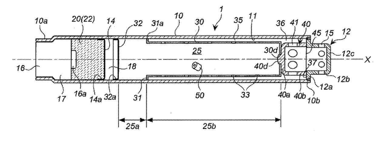
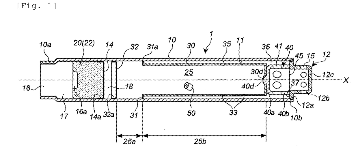
[0041]The present invention provides a gas generator in which an advantageous effect of collecting a combustion residue in a combustion gas generated by combustion of a gas generating agent is enhanced.

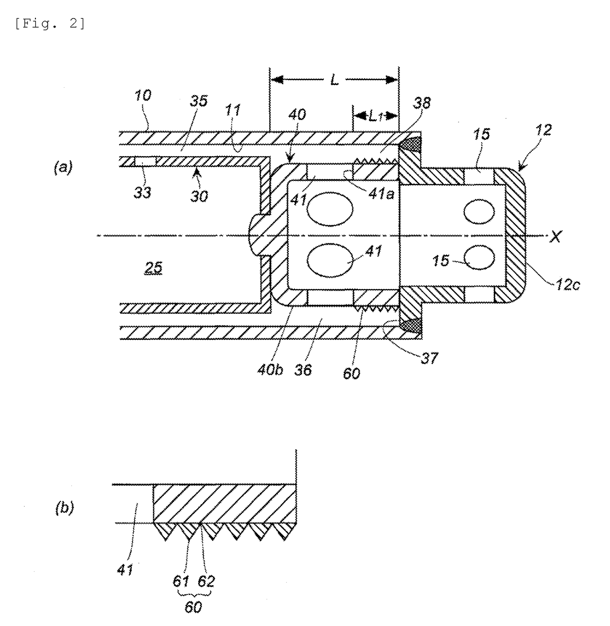
[0042]The gas generator of the present invention has a annular pocket portion as means for collecting a combustion residue (including mist) generated by combustion of a gas generating agent. By contrast with the gas generators of the inventions disclosed in JP-A No. 2011-157025, U.S. Pat. No. 8,376,400, JP-A No. 2010-184559, JP-A No. 2010-264773 and JP-A No. 2014-156207, the gas generator of the present invention uses the pocket portion in which at least a part of its inner circumferential surface has the concave-convex portion.

[0043]Further, in the gas generator of the present invention, a filter, which is disposed in a gas discharge path for the gas flow of the combustion gas passing through from the upstream side to the downstream side (that is, the gas flows only in one direction)...


PUM


Abstract

The present invention provides a gas generator including a cylindrical housing in which an ignition device is attached at a first end portion thereof and a diffuser portion provided with a gas discharge port is attached at a second end portion thereof, an annular end surface being formed on the side of the second end portion, a cylindrical flow path forming member being disposed in the cylindrical housing, an inner space of the cylindrical flow path forming member being partitioned by a partition wall into a first chamber on the side of the first end portion and a second chamber on the side of the second end portion, a space, which includes the first chamber, being a combustion chamber filled with a gas generating agent, and the second chamber forming part of a gas discharge path, in the cylindrical flow path forming member, a first cylindrical space, which is formed between a first wall surface of the cylindrical flow path forming member on the side of the first chamber and the inner wall surface of the cylindrical housing, and a second cylindrical space, which is formed between a second wall surface of the cylindrical flow path forming member on the side of the second chamber and the inner wall surface of the cylindrical housing, being continuous in an axial direction, and the second cylindrical space being a cylindrical space with a length L from a boundary with the first cylindrical space to the annular end surface, and having an annular pocket portion with a length L1 from the annular end surface to the second communication holes, and at least part of a surface of the annular pocket portion being provided with a concave-convex portion.

Description

TECHNICAL FIELD[0001]The present invention relates to a gas generator used for an airbag apparatus of an automobile or the like.DESCRIPTION OF RELATED ART[0002]Gas generators, in which a gas generating agent is a gas generating source, are widely used in airbag apparatuses of automobiles or the like.[0003]In some cases, a combustion residue, which includes a mist of a metal in a molten state derived from a component of the gas generating agent, is generated in a combustion gas produced by combustion of the gas generating agent.[0004]If such a combustion residue is directly discharged from the gas generator and enters an airbag, the airbag can be damaged. For this reason, a filter is usually disposed in a gas discharge path (that is, a flow path for the combustion gas) leading the high-temperature combustion gas generated in the gas generator to a gas discharge port to be discharged. The high-temperature combustion gas is cooled and the combustion residue is collected therefrom when ...

Claims


Application Information

Patent Timeline
IPC IPC(8): B60R21/264
CPCB60R21/264B60R21/261B60R21/2346B60R2021/26011
Inventor HANANO, TEPPEIYAMAZAKI, MASAYUKI
Owner DAICEL CHEM IND LTD
Features
  • R&D
  • Intellectual Property
  • Life Sciences
  • Materials
  • Tech Scout
  • Unparalleled Data Quality
  • Higher Quality Content
  • 60% Fewer Hallucinations
Learn More