Pipe joint

Inactive Publication Date: 2017-12-14
IFOG CO LTD TW
View PDF2 Cites 4 Cited by
  • Summary
  • Abstract
  • Description
  • Claims
  • Application Information

AI Technical Summary

Benefits of technology

[0006]It is therefore a main objective of the present invention to provide

Problems solved by technology

Besides, when there is a need to separate the pipe from the connector, these two p

Method used


Image

  • Pipe joint
  • Pipe joint
  • Pipe joint

Examples


first embodiment

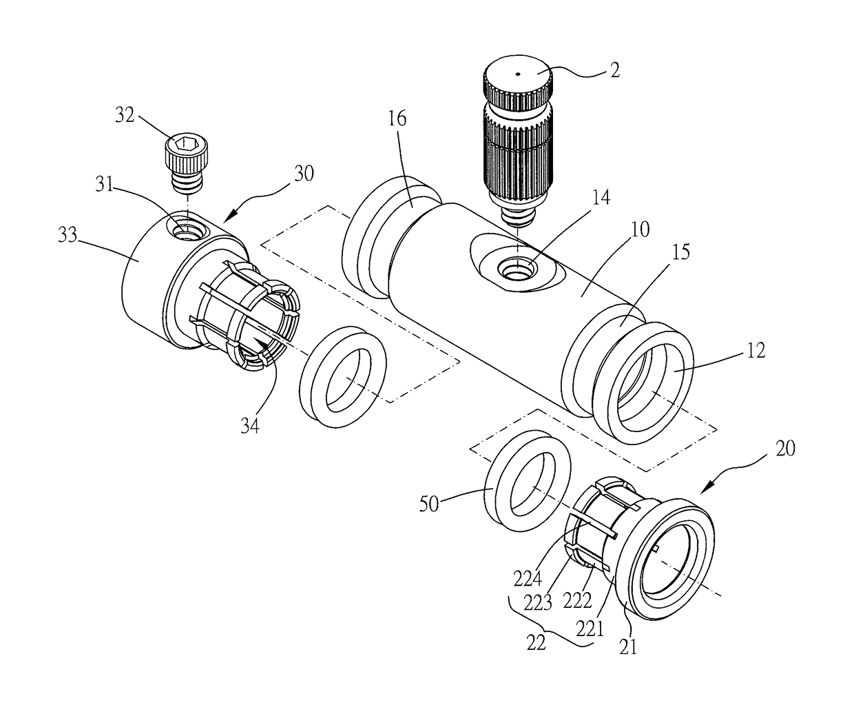
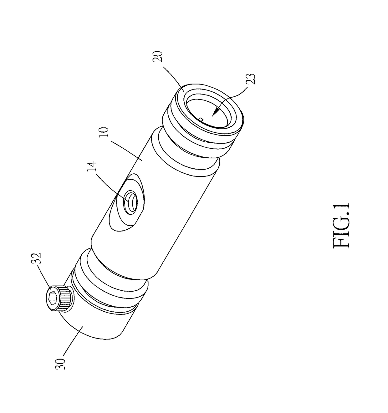
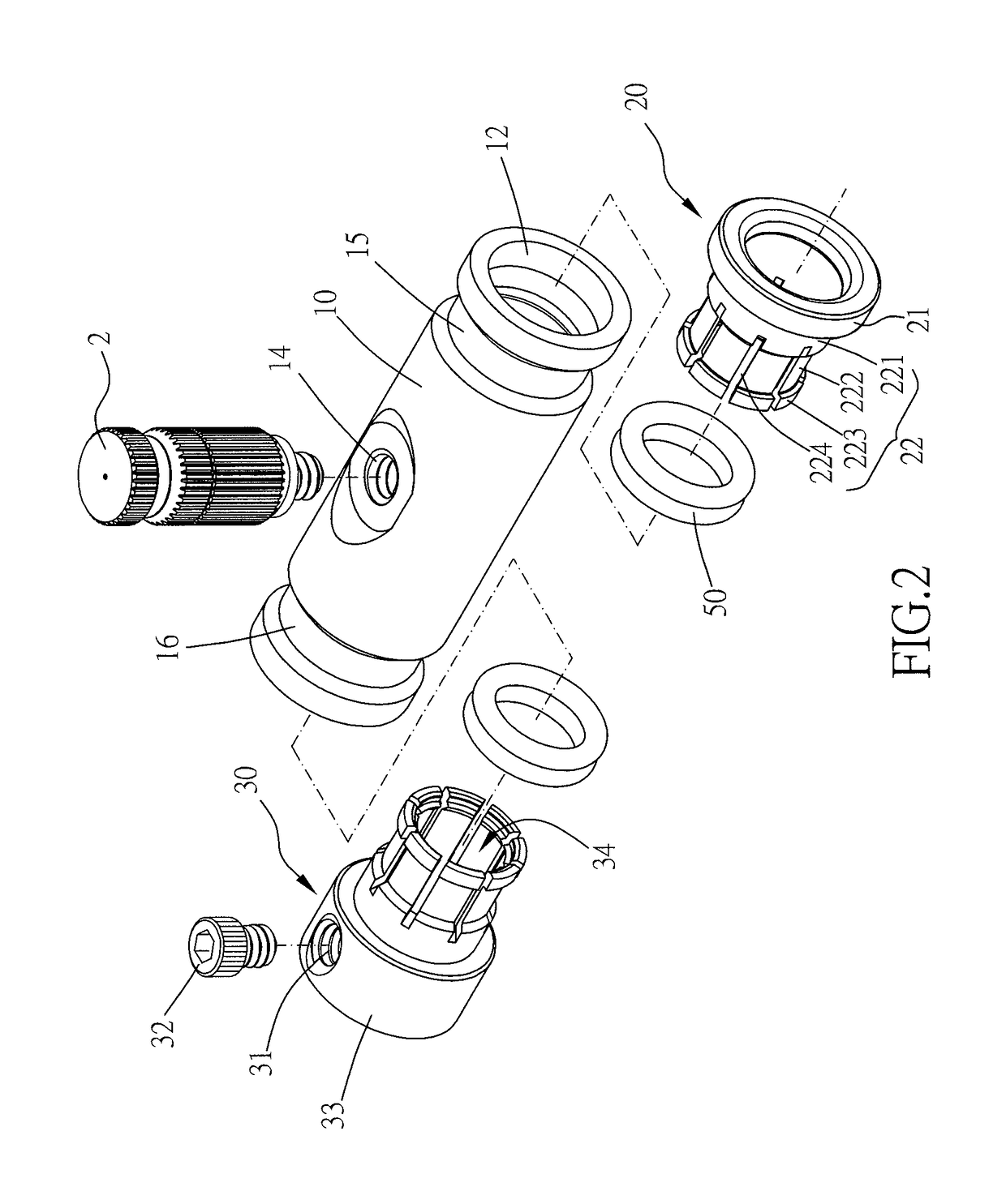
[0036]Please refer to FIGS. 1 to 3 for a pipe joint in accordance with the present invention. The pipe joint includes a main body 10, a positioning socket 20 and another positioning socket 30.

[0037]The main body 10 has a runner 11, an opening 12, another opening 13, a nozzle connecting bore 14, a recess 15 and another recess 16. The openings 12, 13 are located on opposite ends of the runner 11. The nozzle connecting bore 14 is adapted for a nozzle 2 to couple therewith. The recesses 15, 16 are formed on the outer periphery of the main body 10 and are adjacent to openings 12, 13 respectively. Each recess has two side walls for a clamping tool to abut thereagainst.

[0038]The runner 11 has an insertion area 112 adjacent to the opening 12, another insertion area 113 adjacent to the opening 13, an inner stopping lip 114 adjacent to the insertion area 112 and another inner stopping lip 115 adjacent to the insertion area 113. Preferably, the insertion areas 112, 113 radially align with the ...

third embodiment

[0052]In the aforementioned embodiments, the main body is in tubular shape and has two openings on two opposite ends. In other possible embodiments, the main body can also be in L-shape, T-shape, X-shape or other shapes that has multiple openings, not limited to two. The main body may also be formed without any nozzle connecting bores. For instance, FIG. 11 shows a main body 10 in accordance with the present invention, in which the main body 10 has only one opening and no nozzle connecting bores. This type of pipe joints is suitable to be installed at tubing ends of the piping system.


PUM


Abstract

A pipe joint for coupling to at least one pipe is disclosed in the present invention. The pipe joint includes a main body and at least one positioning socket. The main body has a runner and at least one opening communicated with the runner. The runner has an insertion area adjacent to the opening. The positioning socket has a head, an inserting portion, a pipe channel, a radial threaded hole and a bolt. The inserting portion is inserted into the runner via the opening. The pipe channel runs through the head and the inserting portion in an axial direction of the positioning socket. The threaded hole is formed on the head and communicated with the pipe channel. The bolt is adapted to engage with the threaded hole for abutting against the outer surface of the pipe.

Description

BACKGROUND OF THE INVENTION1. Field of the Invention[0001]The present invention relates generally to a pipe joint of a piping system for connecting hard pipes or soft pipes.[0002]2. Description of the Related Art[0003]Pipe joints are commonly seen at intersections of pipes, turning points or tubing ends of piping systems. It is generally required that the pipe joints have the characteristics that can tightly fit the pipes without leakage. In addition, the pipe joints also need the ability that the pipes can be easily attached thereto or detached therefrom.[0004]Taiwan Patent No. M475540 discloses a “push-in connector for pipes and piping systems,” in which the main body thereof has slidable resilient locking rings and positioning sockets on both ends. The positioning sockets can grip with the outer surface of the pipe with its teeth formed at the distal end thereof, such that the pipe can be fixed in position.[0005]Nevertheless, the teeth formed on the resilient arms are suitable fo...

Claims


Application Information

Patent Timeline
IPC IPC(8): F16L37/02F16L25/06
CPCF16L25/065F16L37/02F16L41/00F16L33/207
Inventor HUANG, MING-CHING
Owner IFOG CO LTD TW
Why Eureka
Try Eureka