Elastic wave device and manufacturing method therefor

a manufacturing method and technology of elastic waves, applied in the manufacture/assembly of piezoelectric/electrostrictive devices, electrical appliances, electric/electrostrictive devices, etc., can solve the problems of unwanted waves degrading resonance characteristics, filter characteristics, and unwanted waves to be used but also reflected, so as to reduce or prevent the reflection of unwanted waves, reduce the influence of unwanted waves, and reduce the effect of unwanted waves

Active Publication Date: 2017-12-21
MURATA MFG CO LTD
View PDF7 Cites 7 Cited by
  • Summary
  • Abstract
  • Description
  • Claims
  • Application Information

AI Technical Summary

Benefits of technology

[0017]A manufacturing method for the elastic wave device according to the second broad aspect of a preferred embodiment of the present invention includes a step of forming the acoustic reflection layer on the piezoelectric layer; and a step of forming the excitation electrode to be in contact with the piezoelectric layer. In a process of forming the acoustic reflection layer, the outer peripheral edges of the individual main surfaces of the pair of main surfaces of the at least one of the high acoustic impedance layer and the low acoustic impedance layer are curved so as not to be located within the surfaces where the individual main surfaces at the center of the at least one of the high acoustic impedance layer and the low acoustic impedance layer are extended in the outer peripheral edge direction. In this case, unwanted waves are irregularly reflected in an effective manner, and influence of the unwanted waves are reduced effectively.
[0018]A manufacturing method for the elastic wave device according to the third broad aspect of a preferred embodiment of the present invention includes a step of forming the acoustic reflection layer on the piezoelectric layer; and a step of forming the excitation electrode to be in contact with the piezoelectric layer. In a process of forming the acoustic reflection layer, the at least one of the high acoustic impedance layer and the low acoustic impedance layer is formed such that the outer peripheral side surface of the at least one of the high acoustic impedance layer and the low acoustic impedance layer is separate from the outer peripheral side surfaces of the other layers with a step therebetween. In this case, by arranging an outer peripheral side surface of at least one layer separately from outer peripheral side surfaces of other layers with a step therebetween, unwanted waves partially cancel each other out. Therefore, influence of the unwanted waves is reduced effectively.
[0019]The elastic wave devices according to the first to third broad aspects of various preferred embodiments of the present invention significantly reduce or prevent reflection of unwanted waves toward a piezoelectric layer side. Therefore, characteristics of the elastic wave devices such as resonance characteristics and filter characteristics are less likely to be degraded.

Problems solved by technology

However, not only elastic waves to be used but also unwanted waves are also reflected.
Therefore, a problem occurs in that the unwanted waves degrade resonance characteristics, filter characteristics, and the like.

Method used


Image

  • Elastic wave device and manufacturing method therefor
  • Elastic wave device and manufacturing method therefor
  • Elastic wave device and manufacturing method therefor

Examples


Embodiment Construction

[0028]Hereinafter, the present invention will become apparent by providing explanation for specific preferred embodiments of the present invention with reference to drawings.

[0029]It is pointed out that preferred embodiments described herein are examples, and partial replacement or combination of configurations in different preferred embodiments is possible.

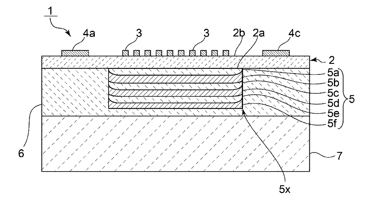
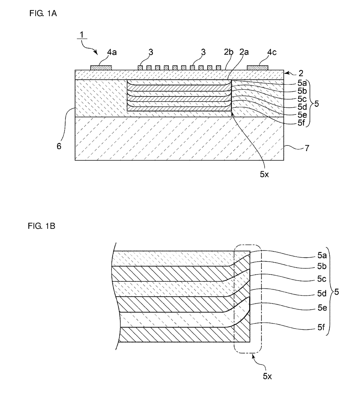
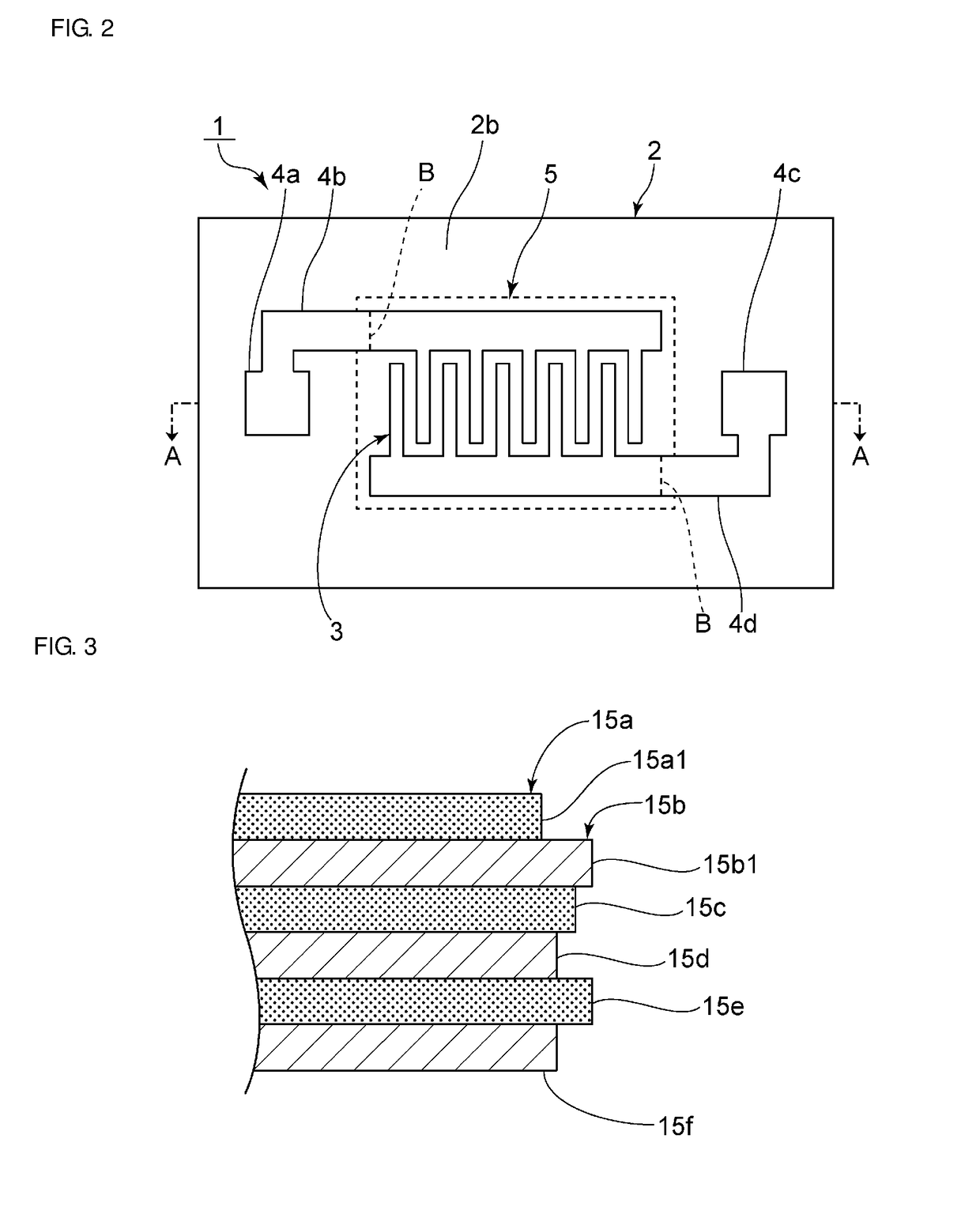
[0030]FIG. 1A is a front cross-sectional view of an elastic wave device according to a first preferred embodiment of the present invention, and FIG. 1B is a partially cut-out front cross-sectional view which illustrates a main portion of the elastic wave device in an enlarged manner. FIG. 2 is a plan view of the elastic wave device according to the first preferred embodiment. FIG. 1A corresponds to a cross section taken along line A-A of FIG. 2.

[0031]An elastic wave device 1 is not particularly limited. However, the elastic wave device 1 preferably is an elastic wave device that uses plate waves. The elastic wave device 1 include...


PUM


Abstract

An elastic wave device in which an IDT electrode defines an excitation electrode on a piezoelectric layer, an acoustic reflection layer is laminated on a first main surface of the piezoelectric layer, the acoustic reflection layer includes high acoustic impedance layers with a relatively high acoustic impedance and low acoustic impedance layers with a relatively low acoustic impedance, and the acoustic reflection layer has an unwanted wave reflection suppression structure in which reflection of unwanted waves toward the piezoelectric layer side is significantly reduced or prevented.

Description

[0001]This application claims the benefit of priority to[0002]Japanese Patent Application No. 2015-051815 filed on Mar. 16, 2015 and is a Continuation Application of PCT Application No. PCT / JP2016 / 051030 filed on Jan. 14, 2016. The entire contents of each application are hereby incorporated herein by reference.BACKGROUND OF THE INVENTION1. Field of the Invention[0003]The present invention relates to an elastic wave device and a manufacturing method therefor.2. Description of the Related Art[0004]Various elastic wave devices using bulk waves or plate waves have been suggested. Regarding elastic wave devices of this type, a structure in which a cavity is omitted by providing an acoustic reflection layer has been known. For example, in an elastic wave device described in International Publication No. WO 12 / 086441, an IDT electrode is formed on one main surface of a piezoelectric layer, and an acoustic reflection layer is laminated on the other main surface of the piezoelectric layer. T...

Claims


Application Information

Patent Timeline
Patent Type & Authority Applications(United States)
IPC IPC(8): H03H9/02H03H3/10H01L41/047H01L41/29
CPCH03H9/02842H03H9/0211H01L41/29H01L41/047H03H3/10H03H3/02H03H9/02228H03H9/175H03H2003/025H03H3/08H03H9/145H03H9/17H03H9/25H10N30/06H10N30/87
Inventor KISHIMOTO, YUTAKAOMURA, MASASHI
Owner MURATA MFG CO LTD
Why Eureka
Try Eureka