Magnetic resonance apparatus with sound absorption cladding and irregular grid

a technology of magnetic resonance apparatus and irregular grid, applied in the direction of using reradiation, magnetic variable regulation, instruments, etc., can solve the problems of high noise level of magnetic resonance apparatus, high noise level of operating noise, unpleasant effect, etc., and achieve the effect of time-saving and constructionally simple fastening of the cladding uni

Inactive Publication Date: 2016-11-08
SIEMENS HEALTHCARE GMBH
View PDF23 Cites 3 Cited by
  • Summary
  • Abstract
  • Description
  • Claims
  • Application Information

AI Technical Summary

Benefits of technology

[0007]It is proposed that the cladding unit comprises at least one first layer, which includes a sound absorption element, and at least one second layer, which includes a heavy mass layer. A heavy mass layer is to be understood in this context to mean a mass layer which has a density, such as a surface density, of at least 3 k g / m2 or a surface density of approximately 5 kg / m2. The heavy mass layer can be formed for instance of a PVC material and / or an EPDM (ethylene propylene diene monomer) material and / or a silicon material and / or further materials with a high surface density which appear meaningful to the person skilled in the art. The sound absorption element is formed of a soft foam, wherein a sound absorption element is herewith to be understood to mean an absorption element, which is designed to convert sound energy from sound waves into oscillation energy of inaudible oscillation waves, and accordingly to reduce or prevent a reflection of audible sound waves on a boundary surface. The sound waves, such as the air-borne sound waves, cause individual particles, such as for instance foam particles, of the sound absorption element, to oscillate, wherein a generated oscillation energy within the sound absorption element is converted into thermal energy. Oscillation energy is then taken from the sound waves, such as the air-borne sound waves and dampens the air-borne sound waves. A dampening and / or decoupling of the sound waves within the housing unit can take place by this embodiment and in such a way an emission of sound waves from the housing unit can be minimized during operation of the magnetic resonance apparatus. An embodiment of the housing unit of this type brings about a noise reduction during operation of the magnetic resonance apparatus of up to 10 dB compared with conventional rigid housing shells of magnetic resonance apparatuses.
[0010]In a development of the application, it is proposed that the first layer has a layer thickness of at least 5 mm and a maximum of 10 mm, however a layer thickness of approximately 6.5 mm is preferred. The cladding unit can herewith be structured thinly and in addition a material thickness for absorption of sound waves within the cladding unit, such as within the sound absorption layer, can be achieved and in this way a high sound wave dampening within the cladding unit can be achieved.
[0012]It is furthermore proposed that the housing unit has a lacquer coat, which is arranged on a side of the heavy mass layer which faces away from the magnet unit. A surface of the magnetic resonance apparatus which is visible to a patient and / or operator can herewith be integrated in a compact and component-saving manner within the cladding unit.
[0015]In a further embodiment of the application, it is proposed that the irregular grid-type support structure unit has a fine-meshed support structure with several irregularly arranged recesses, which are surrounded in each instance by support structure elements, wherein the support structure elements each have a length of at least 5 cm and a maximum of 20 cm along a recess. The support structure elements framing the recesses comprise however a length of approximately 10 cm to 15 cm along the recess, so that the recesses have a maximum cross-section between two opposite support structure elements framing the recesses of 20 cm and of a maximum of 15 cm. Contact protection can be achieved between the cladding unit and mechanically moveable components and / or electrical components of the magnet unit. Extrusion of the cladding unit up to an outer wall of the magnet unit can herewith be prevented on account of the fine-meshed support structure unit. The fine-meshed support structure unit is designed such that together with the cladding unit, it withstands a compressive force of at least 25 kg with a test pin, which has a diameter of 30 mm. The fine-meshed support structure is arranged on at least one front side and / or rear side of the magnet unit, so that protection of live components can be achieved.
[0016]A constructively simple and time-saving fastening of the cladding unit to the support structure unit can be achieved if the housing unit comprises at least one latching element, by which the cladding unit is fastened to the support structure unit. Alternatively, further fastening elements appearing meaningful to the person skilled in the art can be used at any time to fasten the cladding unit to the support structure unit, such as for instance a Velcro fastener between the cladding unit and the support structure unit and / or a fastening by an expanding rivet.

Problems solved by technology

During operation, magnetic resonance apparatuses generate high levels of noise, which can have an unpleasant effect on a patient occupying an imaging area of the magnetic resonance apparatus for an examination.
These high levels of operating noise are generated within a magnet unit of the magnetic resonance apparatus on account of interaction between a gradient unit and a magnet.

Method used


Image

  • Magnetic resonance apparatus with sound absorption cladding and irregular grid
  • Magnetic resonance apparatus with sound absorption cladding and irregular grid
  • Magnetic resonance apparatus with sound absorption cladding and irregular grid

Examples


Embodiment Construction

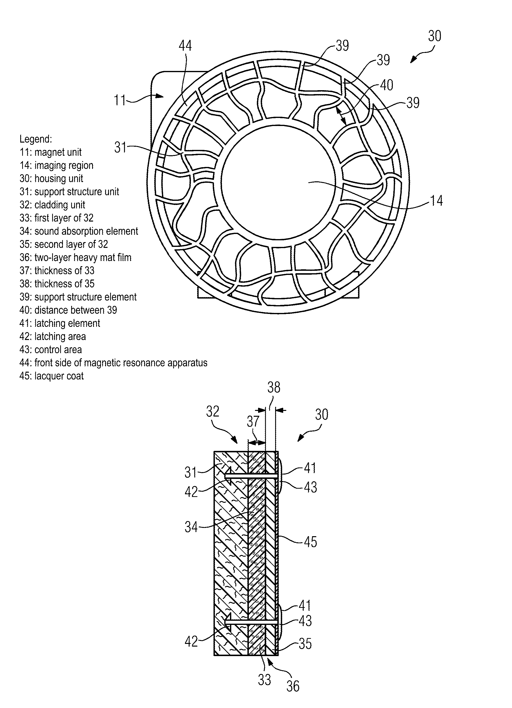
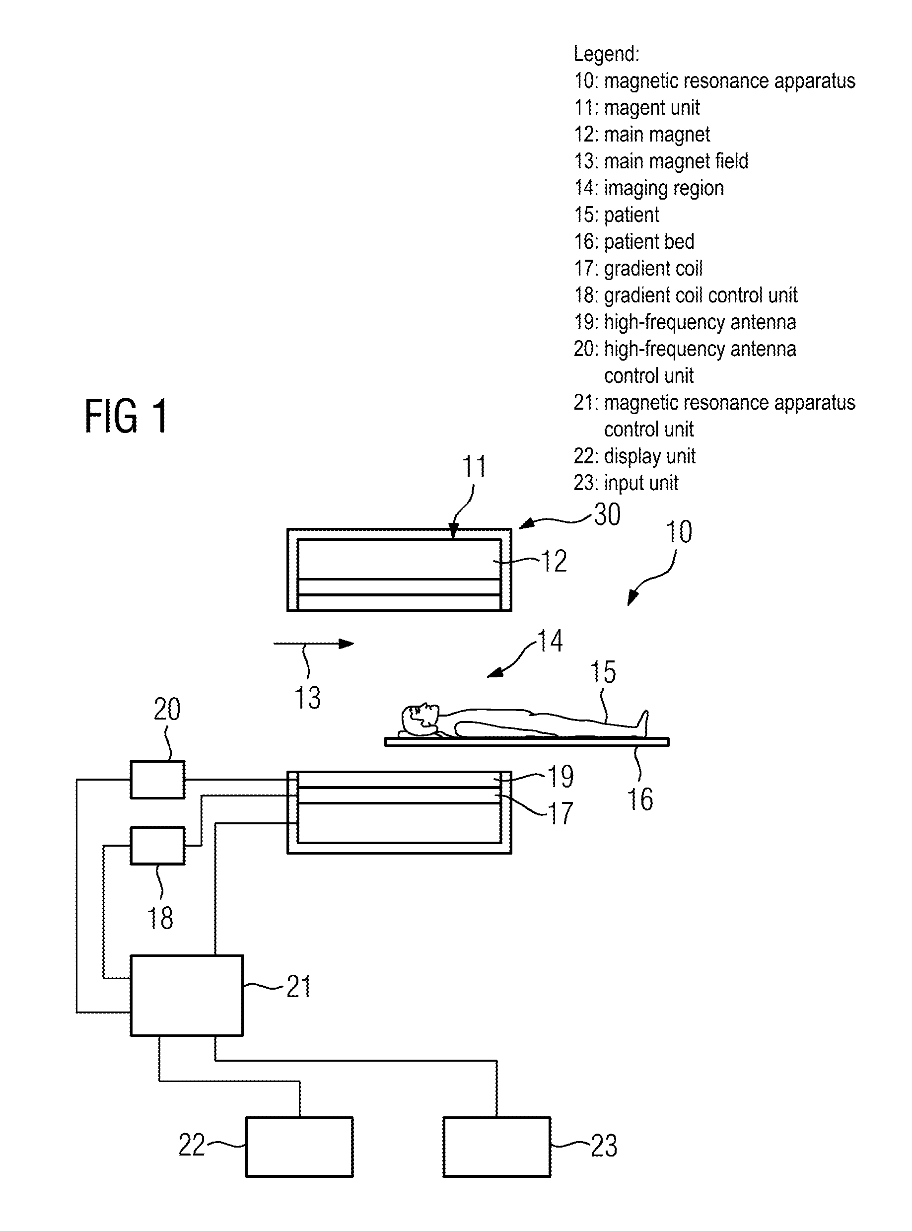
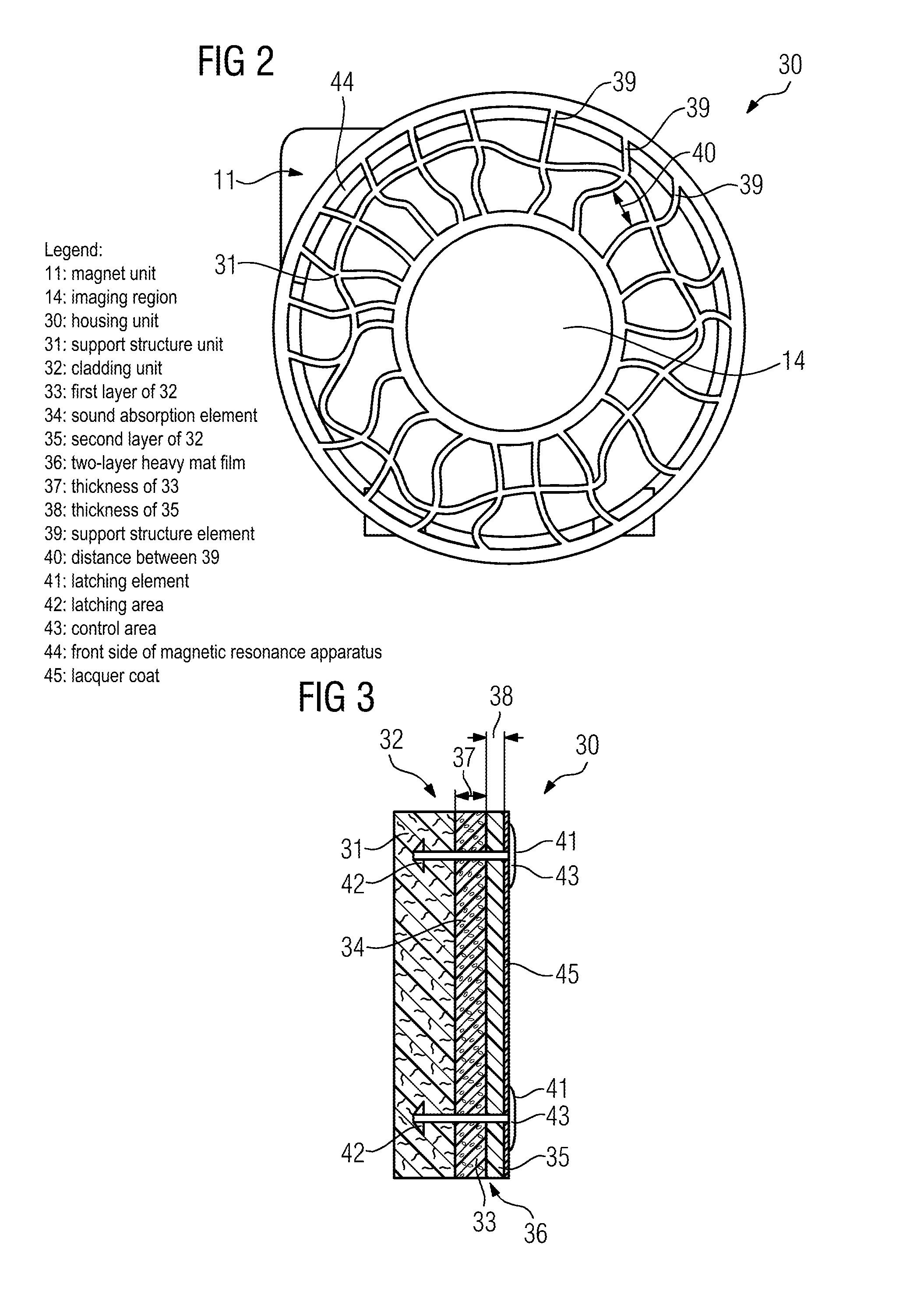
[0021]A disclosed magnetic resonance apparatus 10 is shown schematically in FIG. 1. The magnetic resonance apparatus 10 includes a magnet unit 11 with a main magnet 12 for generating a strong and constant main magnetic field 13. Furthermore, the magnetic resonance apparatus 10 also comprises a cylindrical receiving area 14 for receiving a patient 15, wherein the receiving area 14 is enclosed in a circumferential direction by the magnet unit 11. The patient 15 can be moved into the receiving area 14 by a patient couch 16 of the magnetic resonance apparatus 10. The patient couch 16 is to this end arranged so as to be moveable within the magnetic resonance apparatus 10. Furthermore, the magnetic resonance apparatus 10 comprises a housing unit 30 surrounding the magnet unit 11.

[0022]The magnet unit 11 furthermore comprises a gradient coil 17 for generating magnetic field gradients, which are used for a local encoding during an imaging process. The gradient coil 17 is controlled by a gra...


PUM


Abstract

A magnetic resonance apparatus is proposed. The magnetic resonance apparatus has a magnet unit, magnet housing and a housing unit surrounding the magnet unit. The housing unit includes at least one support structure unit and a cladding unit. The cladding unit has at least one first layer, which includes a sound absorption element, and at least one second layer, which includes a heavy mass layer.

Description

CROSS REFERENCE TO RELATED APPLICATION[0001]This application claims priority of German application No. 10 2011 082 402.2 filed Sep. 9, 2011, which is incorporated by reference herein in its entirety.FIELD OF INVENTION[0002]The present application relates to a magnetic resonance apparatus with a magnet unit and a housing unit surrounding the magnet unit, said housing unit having at least one support structure unit and a cladding unit.BACKGROUND OF INVENTION[0003]During operation, magnetic resonance apparatuses generate high levels of noise, which can have an unpleasant effect on a patient occupying an imaging area of the magnetic resonance apparatus for an examination. These high levels of operating noise are generated within a magnet unit of the magnetic resonance apparatus on account of interaction between a gradient unit and a magnet. Sound waves are transmitted in such cases within the magnetic resonance apparatus by an air-borne sound excitation and also by way of solid-borne so...

Claims


Application Information

Patent Timeline
Patent Type & Authority Patents(United States)
IPC IPC(8): G01R33/28
CPCG01R33/28
Inventor HIERL, ANDREASMACIEJEWSKI, BERNDSTEIN, ANNETTE
Owner SIEMENS HEALTHCARE GMBH
Why Eureka
Try Eureka