Patterned layer for absorbent article

Inactive Publication Date: 2005-06-30
SCA HYGIENE PROD AB
View PDF5 Cites 11 Cited by
  • Summary
  • Abstract
  • Description
  • Claims
  • Application Information

AI Technical Summary

Benefits of technology

[0021] As the pattern is preferably made up of separate dots, however, the observer may at too close a distance perceive the pattern in the first state as diffuse because the pattern will then to the perception of the observer be broken up into the separate dots. The distance is therefore significant for the observer perceiving that the dots come together to form the pattern intended by the manufacturer. In the manufacture of the article, account should therefore preferably be taken of all the parameters mentioned above in order to obtain the desired effect of the embodiment, namely an interpretable pattern in a first state of the layer and an uninterpretable and diffuse pattern in a second and then expanded state.

Problems solved by technology

It is true that the text / the pattern disappears as a result of this procedure, but a problem remains, namely that the separate layer which has now been removed has formed a residual product which has to be dealt with.

Method used


Image

  • Patterned layer for absorbent article
  • Patterned layer for absorbent article
  • Patterned layer for absorbent article

Examples


first embodiment

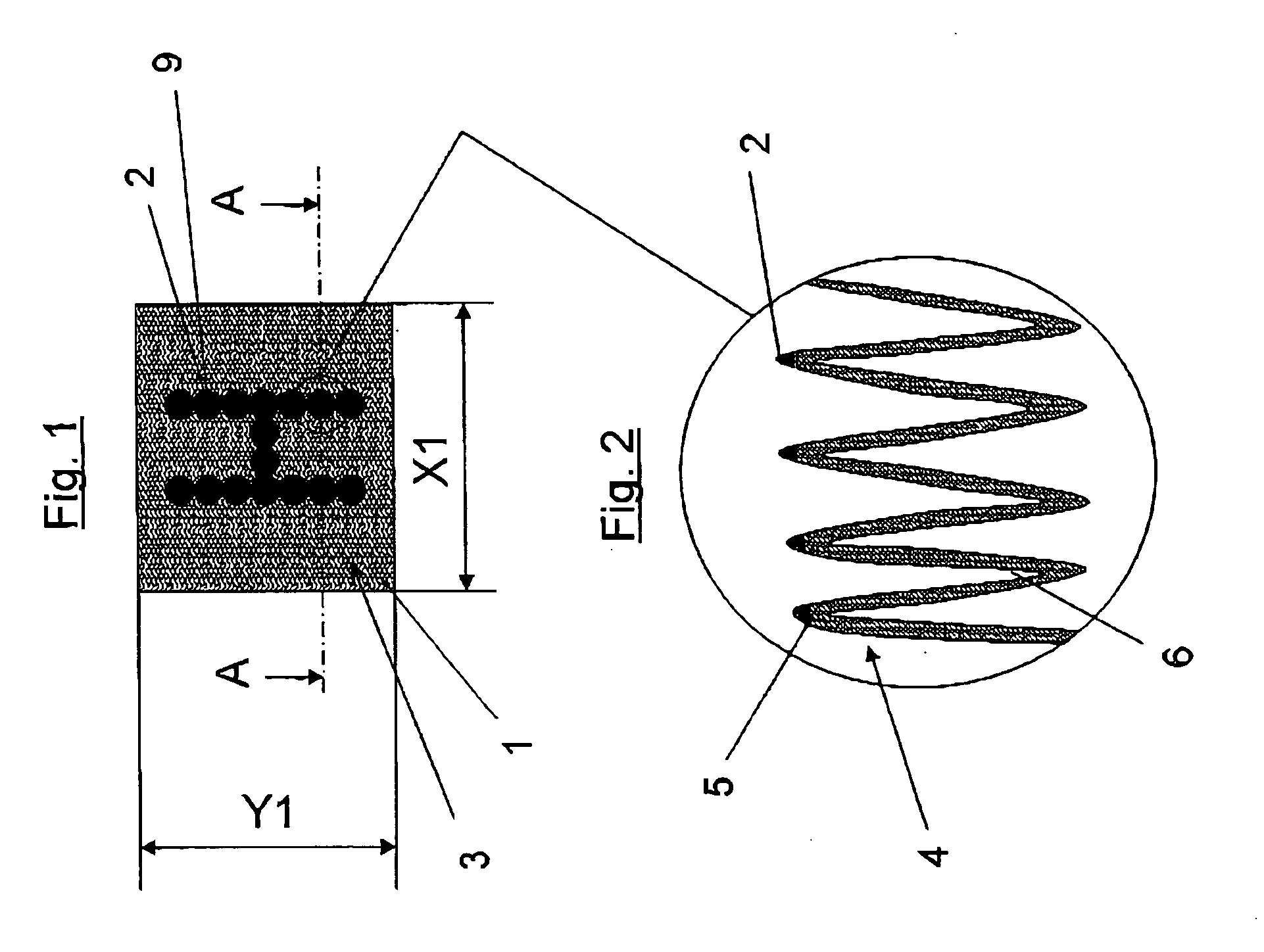
[0034]FIG. 1 shows a first embodiment where a patterned layer 1 with a length X1 (X direction) and a width Y1 (Y direction) is in a first state. Here, the pattern consists of a number of separate black dots 9 which together form the letter H. In FIG. 1, the layer 1 is in a drawn-together state where the layer 1 has puckered. FIG. 1 therefore shows the layer 1 in a puckered first state. The fact of the layer being puckered is marked in FIG. 1 by a wave-shaped pattern 3. The layer can be puckered in the X direction, the Y direction or both the X direction and the Y direction. The puckered layer 1 comprises elevations and depressions therebetween. In FIG. 1, the dots 9 have been formed by dye having been applied at points to the layer in such a way that a number of the wave-shaped elevations have been dyed when the layer 1 is in the puckered state. This will be explained in greater detail in connection with FIG. 2.

[0035]FIG. 2 shows an enlarged portion of a part of the layer 1 accordin...

second embodiment

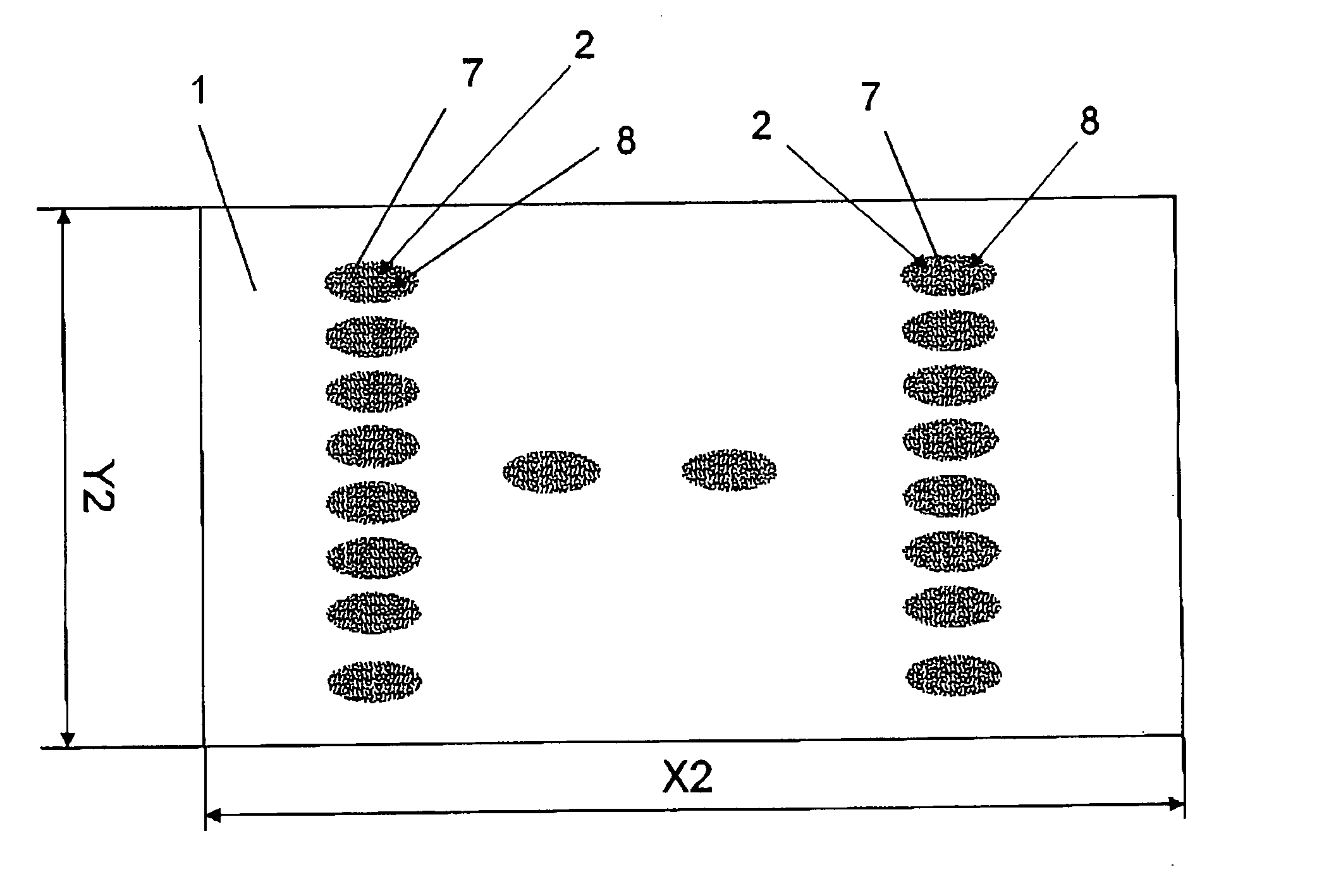
[0039]FIG. 4 shows a second embodiment where the dye is applied at points to a layer 1 which is in the second state, that is to say in an expanded state where the layer has the length X2 and the width Y2. The dye is applied in the form of separate dots 9. In the second state, the dots 9 are located at such a spacing from one another than the pattern H is perceived by an observer as diffuse and unclear. FIG. 4 shows moreover that the layer has been stamped with impressions 10 in the form of a punctiform pattern, where only a number of the punctiform impressions 10 have been dyed to form the dots 9. The punctiform impressions 10 can constitute a three-dimensional pattern in a layer but can also constitute bonding points between two layers. The punctiform impressions 10 can be brought about by, for example, one or more layers being guided between a stamping roller and an opposite ultrasound device or an opposite counterstay roller. PCT SE03 / 01959 indicates an advantageous method of int...

third embodiment

[0043]FIG. 7 shows a third embodiment where the dye is applied at points to a plane or smooth layer 1 which is in the first state, that is to say in a contracted state where the layer 1 has the length X1 and the width Y1. The dye is applied in the form of separate dots 9. In the first state, the pattern H appears clearly for an observer on account of the fact that the spacing between the dots 9 is so small that, for an observer, the dots come together to form the pattern H. FIG. 7 shows that the layer 1, like the layer in FIG. 4, has been stamped with impressions 10 in the form of a punctiform pattern, where only a number of the punctiform impressions 10 have been dyed. Here too, the punctiform impressions 10 can constitute a three-dimensional pattern in a layer but can also constitute bonding points between two layers.

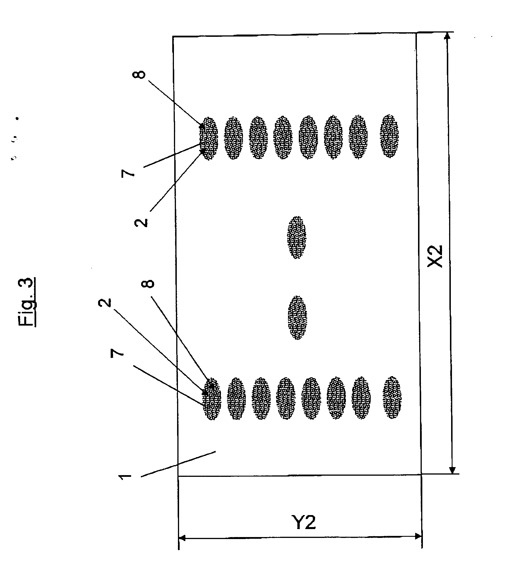
[0044]FIG. 8 shows a layer 1 according to FIG. 7 in the second state, that is to say when the layer has the length X2 and the width Y2. In the second state, the dots ...


PUM


Abstract

A patterned layer is intended to be used in an absorbent article, and has a pattern, for example in the form of a text or an image, which appears clearly legible or interpretable for an observer at a certain distance. The pattern can be formed by a number of dots which, when the layer is in a first state, have a first surface density which forms the legible or interpretable pattern and which, when the layer is in a second and then expanded state, have a second surface density which is lower than the first surface density in the first state, the pattern becoming in the second state essentially illegible or uninterpretable for the observer at the given distance on account of the lower surface density.

Description

CROSS-REFERENCE TO RELATED APPLICATION [0001] The present application claims the benefit of U.S. Provisional Application Ser. No. 60 / 531,037, filed on Dec. 22, 2003.TECHNICAL FIELD [0002] The invention relates to a patterned layer intended to be used in an absorbent article, having a pattern, for example in the form of a text or an image, which appears legible or interpretable for an observer at a certain distance. BACKGROUND [0003] In absorbent articles such as diapers, sanitary towels, incontinence pads etc., it is known to apply texts and / or patterns to certain layers included in the article. The texts are preferably of an informative nature, for example in the form of user instructions or a warning text. The pattern is preferably in the form of a decorative pattern and / or in the form of a handling example. The texts and the pattern are usually arranged on one of the layers which form the outside of the article, for example on the front panel, the rear panel or one of the side pa...

Claims


Application Information

Patent Timeline
Patent Type & Authority Applications(United States)
IPC IPC(8): A61F13/15A61F13/20
CPCA61F13/49009A61F13/514B41J2/005A61F2013/8497A61F13/84
Inventor LINDER, MICHAEL
Owner SCA HYGIENE PROD AB
Why Eureka
Try Eureka