
Non-pneumatic tire with multi-connection connecting elements

a technology of connecting elements and non-pneumatic tires, which is applied in the direction of high-resiliency wheels, tire parts, vehicle components, etc., can solve the problems of low tire strength, lack of performance advantages, and difficulty in maintenance and repair

Inactive Publication Date: 2017-12-28
MICHELIN & CO CIE GEN DES ESTAB MICHELIN
View PDF1 Cites 8 Cited by
  • Summary
  • Abstract
  • Description
  • Claims
  • Application Information

AI Technical Summary

Benefits of technology

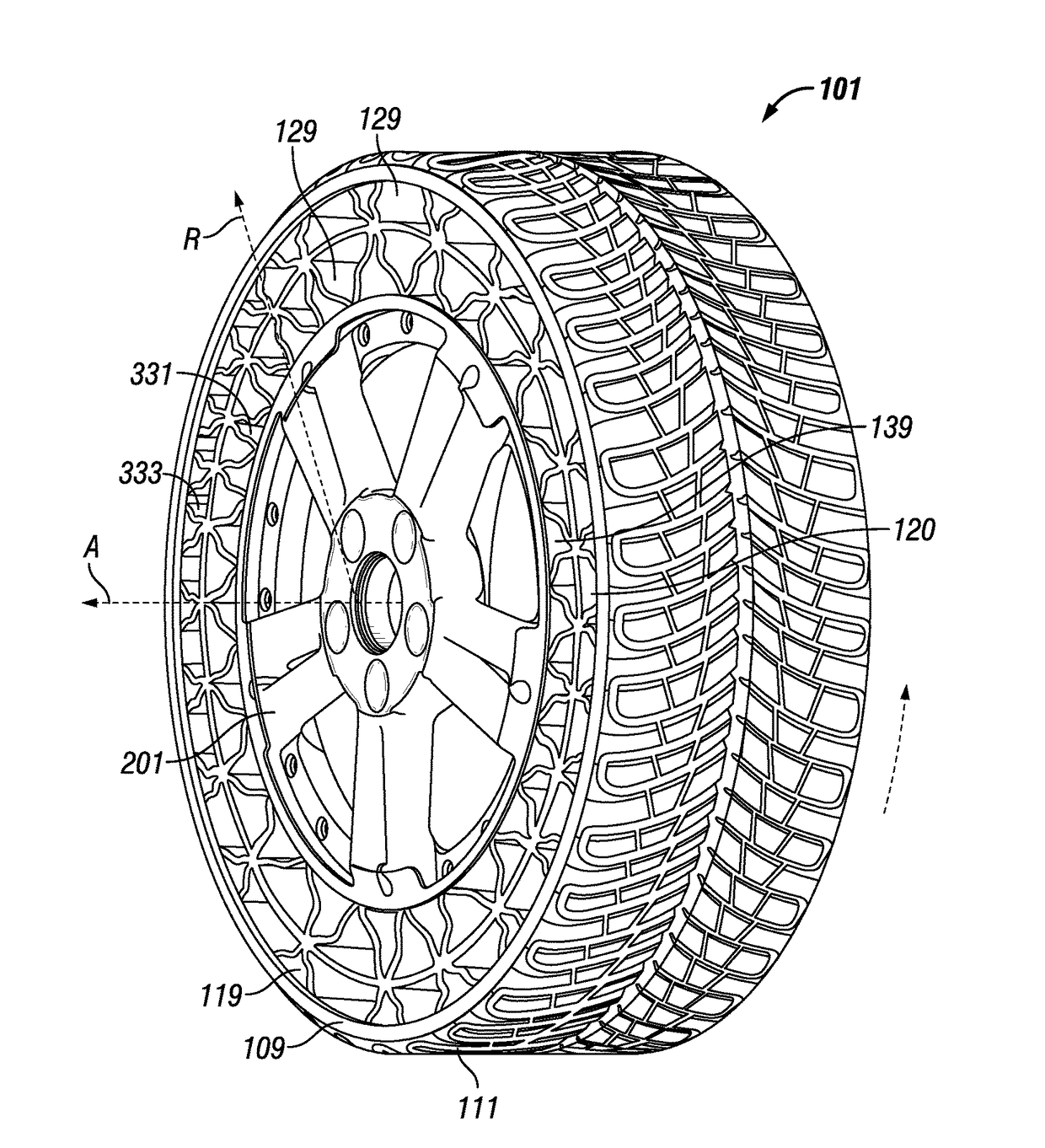
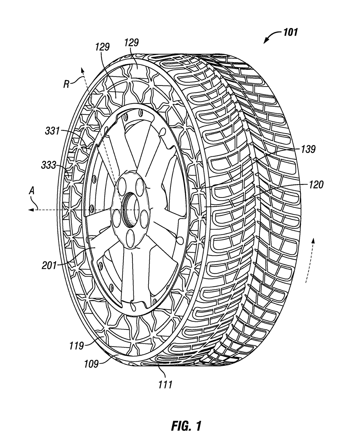
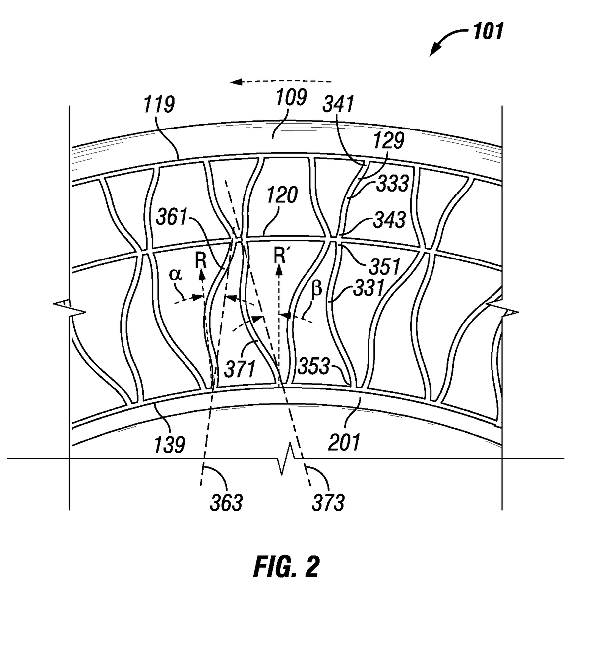
The invention is a non-pneumatic tire that includes a hub, an outer band, connecting members, and an intermediate band. The connecting members have a curvilinear shape that includes a radially inner and outer segment end. The tire may have multiple rows of connecting members or just one. The intersection points of the connecting members with the intermediate band form a first set of connecting member segments and a second set of connecting member segments. The majority of each connecting member segment is positioned on one side of an imaginary straight line segment between the inner and outer segment ends. This design allows for improved tire performance and stability.

Problems solved by technology

The pneumatic tire is the best known solution for compliance, comfort, mass, and rolling resistance; however, the pneumatic tire has disadvantages in complexity, the need for maintenance, and susceptibility to damage.
Conventional solid tires, spring tires, and cushion tires, although lacking the need for maintenance and the susceptibility to damage of pneumatic tires, unfortunately lack its performance advantages.
These types of tires can be heavy and stiff and lack the shock absorbing capability of pneumatic tires.
While the hub is thereby suspended by the springs, the inflexible ring has only a small contact area with the road, which offers essentially no compliance, and provides poor traction and steering control.
Reduction in thickness of a web element that is only connected at the hub and at the shear ring on a tire used in a vehicle, such as an automobile, creates a structure that has undesirable dynamic characteristics at highway speeds.

Method used


Image

  • Non-pneumatic tire with multi-connection connecting elements
  • Non-pneumatic tire with multi-connection connecting elements
  • Non-pneumatic tire with multi-connection connecting elements

Examples


Embodiment Construction

[0022]The present invention provides for a non-pneumatic tire having improved high speed performance characteristics. For purposes of describing the invention, reference now will be made in detail to embodiments and / or methods of the invention, one or more examples of which are illustrated in or with the drawings. Each example is provided by way of explanation of the invention, not limitation of the invention. In fact, it will be apparent to those skilled in the art that various modifications and variations can be made in the present invention without departing from the scope or spirit of the invention. For instance, features or steps illustrated or described as part of one embodiment, can be used with another embodiment or steps to yield a still further embodiments or methods. Thus, it is intended that the present invention covers such modifications and variations as come within the scope of the appended claims and their equivalents.

[0023]The following terms are defined as follows ...


PUM


Abstract

A non-pneumatic tire (101) having a hub (201) and a compliant outer band (109) connected by connecting members (129) that are intersected by an intermediate band (120) positioned between the hub (201) and compliant outer band (109) forming a plurality of connecting element segments (331,333), each segment having a predominant curvature extending in the same longitudinal direction said direction coinciding with the preferred direction of rotation of the tire (101).

Description

FIELD OF THE INVENTION[0001]The subject matter of the present disclosure relates generally to tension-based non-pneumatic, structurally supported tires and wheels. More particularly, the invention relates to a tension-based non-pneumatic wheel having load supporting structural elements extending a portion of the width across the tire.BACKGROUND OF THE INVENTION[0002]The pneumatic tire is the best known solution for compliance, comfort, mass, and rolling resistance; however, the pneumatic tire has disadvantages in complexity, the need for maintenance, and susceptibility to damage. A device that improves on pneumatic tire performance could, for example, provide more compliance, better control of stiffness, lower maintenance requirements, and resistance to damage.[0003]Conventional solid tires, spring tires, and cushion tires, although lacking the need for maintenance and the susceptibility to damage of pneumatic tires, unfortunately lack its performance advantages. In particular, soli...

Claims


Application Information

Patent Timeline
Patent Type & Authority Applications(United States)
IPC IPC(8): B60B9/26B60C7/14B60B9/04B60C7/10
CPCB60B9/26B60B9/04B60C7/14B60C2007/146B60C2007/107B60B2900/351B60B2900/111B60B2900/112B60B2900/1212B60B2900/133B60B2900/551B60C7/143B60C7/107B60C7/146
Inventor CRON, STEVEN MRHYNE, TIMOTHY BRETT
Owner MICHELIN & CO CIE GEN DES ESTAB MICHELIN
Learn More