Microwave frequency satellite signal reception installation

a satellite signal and microwave frequency technology, applied in the direction of ghz frequency transmission, broadcast receiving circuit, television system, etc., can solve the problems of limited number of inputs and limited number of switch matrix inputs, and not allowing system chang

Inactive Publication Date: 2010-04-08
EUTELSAT
View PDF5 Cites 7 Cited by
  • Summary
  • Abstract
  • Description
  • Claims
  • Application Information

AI Technical Summary

Benefits of technology

[0015]A known solution to this problem consists of using the technology known as UNICABLE™ to serve several satellite receivers; such a technology is notably described in the standard CENELEC EN 50494 or in patent application FR2835368. This solution consists of having a single down-lead coaxial cable and then of having a distributor (signal division). Each receiver will have a dedicated carrier (known as a “user band”) inside the 950-2150 spectrum operating at a fixed frequency: the content of each frequency is fixe...

Problems solved by technology

However, this solution poses some difficulties; in fact, the switch matrices have a limited number of inputs (typically 4 inputs corresponding to four states coming from a satellite or 8 inputs corresponding to four states coming f...

Method used


Image

  • Microwave frequency satellite signal reception installation
  • Microwave frequency satellite signal reception installation
  • Microwave frequency satellite signal reception installation

Examples


Embodiment Construction

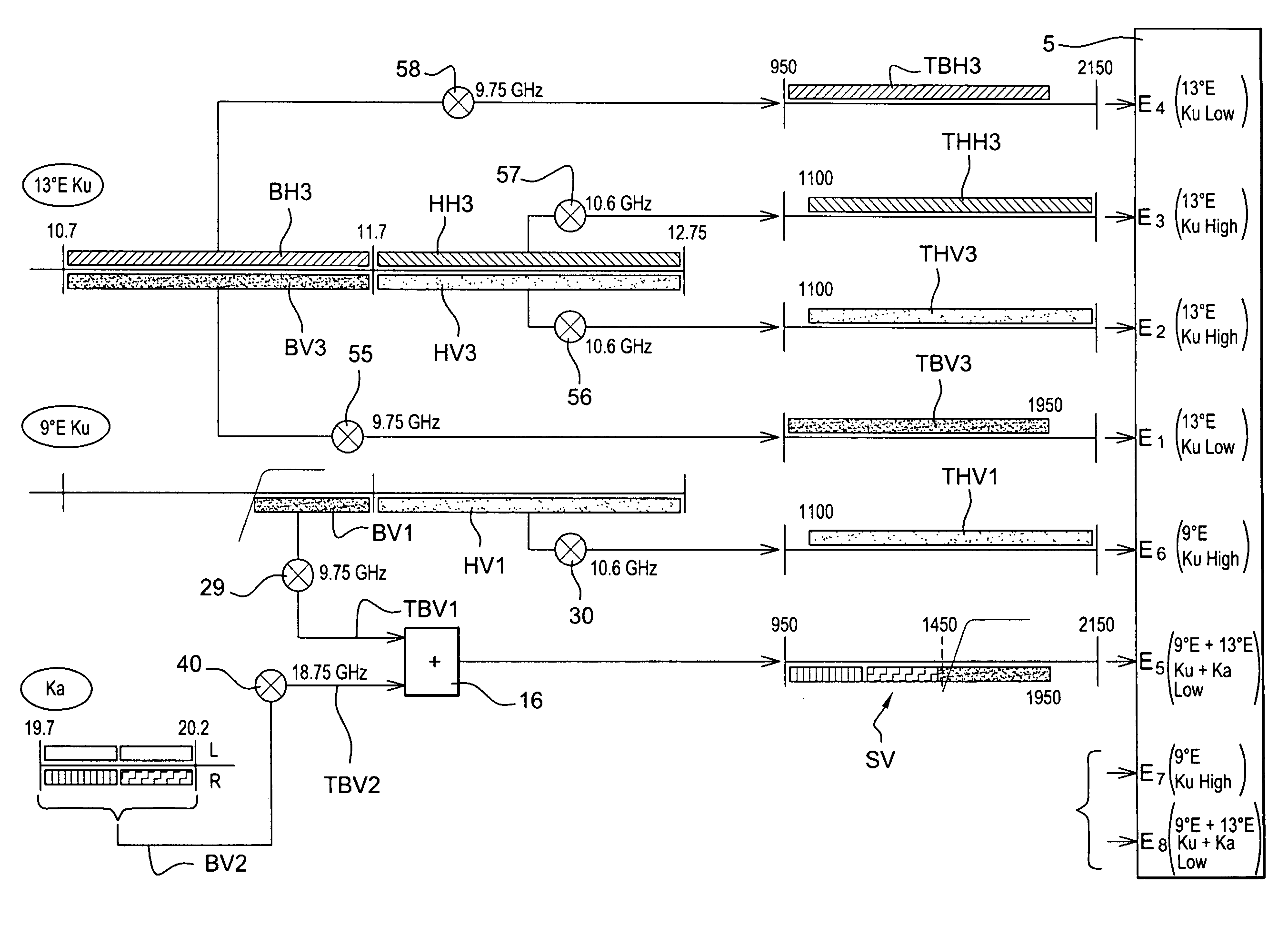
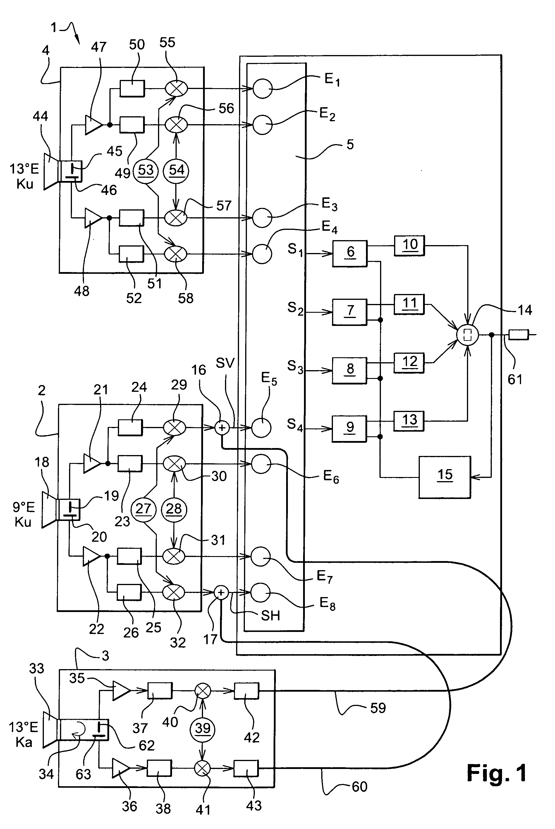
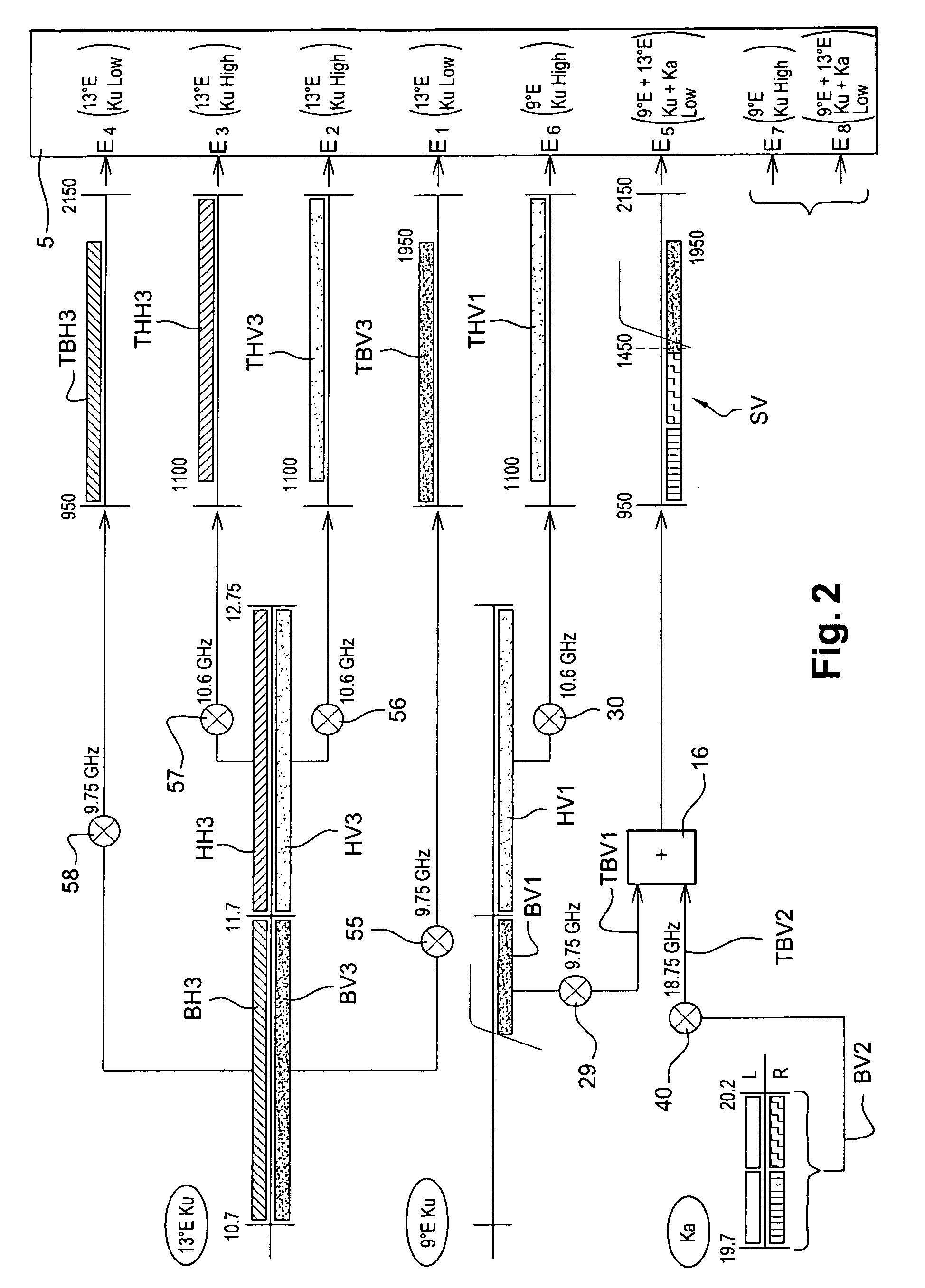
[0110]FIG. 1 represents an installation 1 for receiving radio satellite signals according to the invention. It will be noted that all the orbital positions and frequency bands described in the following are given purely for illustration purposes and that the device according to the invention may of course be applied to other orbital positions of satellites and to other frequency bands. Installation 1 comprises:

[0111]three LNB blocks 2, 3 and 4;

[0112]a selector 5 with eight inputs E1 to E8 and four outputs S1 to S4;

[0113]four mixer blocks 6, 7, 8 and 9,

[0114]four passband filters 10, 11, 12 and 13; a first electric coupler 16;

[0115]a second electric coupler 17;

[0116]a third electric coupler 14;

[0117]a control unit 15.

[0118]Installation 1 is connected via a single coaxial cable 61 to a processing unit, not represented, and is comprised of demodulation blocks, each demodulation block comprising, among other items, a channel selector and a demodulator.

[0119]Installation 1 is adapted for...


PUM


Abstract

The present invention relates to an installation for receiving microwave frequency radio satellite signals, said installation comprising a first electric adder to add a first electrical signal representative of a radio signal according to a first polarization and transposed to a first intermediate band and a second electrical signal representative of a radio signal according to a first polarization and transposed to a second intermediate band and a second electric adder to add a first electrical signal representative of a radio signal according to a second polarization and transposed to the first intermediate band and a second electrical signal representative of a radio signal according to a second polarization and transposed to a second intermediate band.

Description

[0001]This claims the benefits of French Patent Application FR 08 / 56762, filed on Oct. 6, 2008, and hereby incorporated by reference herein.BACKGROUND[0002]The present invention relates to a microwave frequency satellite signal reception installation.[0003]Currently, broadcasting programs by satellite is widely used across the world. Numerous devices are installed in millions of users' homes. The devices installed are predominantly reception devices that comprise an outer unit including a parabolic reflector that focuses the modulated microwave frequency signals onto the source, known as a horn, of an LNB (Low Noise Block), the LNB transforming the microwave frequency signals received into electrical signals in intermediate satellite band in order to transmit them through a coaxial cable to an internal unit, generally called a satellite decoder or even STB (“Set Top Box”). The decoder comprises a demodulation block that extracts a “useful” modulated signal in the modulated signal tr...

Claims


Application Information

Patent Timeline
IPC IPC(8): H04N7/20
CPCH04H40/90
Inventor LOTFY, KAMAL
Owner EUTELSAT
Why Eureka
Try Eureka