

Radio communication apparatus and method
a radio communication and apparatus technology, applied in the field of mobile communication, can solve the problems of increasing the interference between the bands, the interference of the base stations, and the frequency of the base station, so as to improve the frequency use efficiency and prevent the excessive increase of overhead
- Summary
- Abstract
- Description
- Claims
- Application Information
AI Technical Summary
Benefits of technology
Problems solved by technology
Method used
Image

Examples
first embodiment
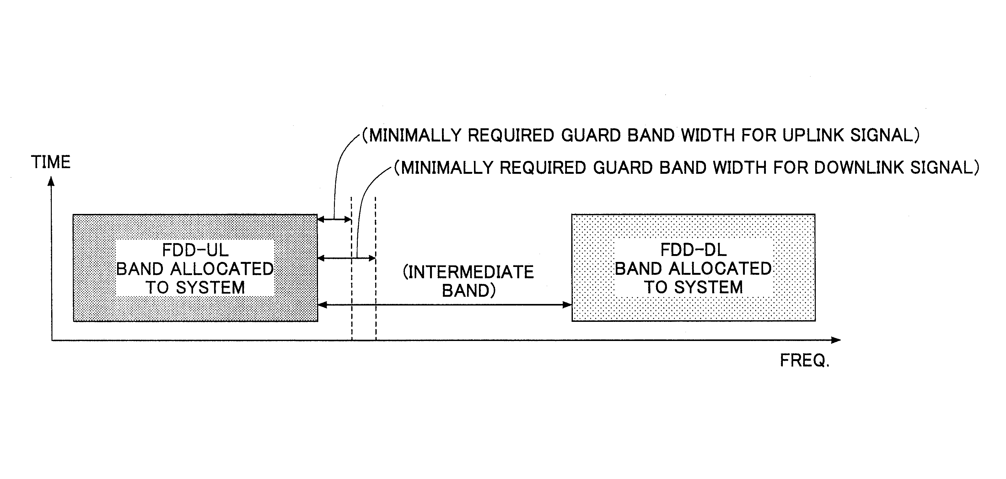
FDD
[0073]In the following, examples of using the intermediate band based on the FDD scheme are described.
[0074]FIG. 8 shows an exemplary configuration of a relay apparatus according to an embodiment of the present invention. In the configuration of FIG. 8, a radio circuit section 802 receives a signal. The signal includes a signal of the system to which the radio apparatus belongs such as data signal to be relayed and a control signal to be relayed, and an interference signal from another system.
[0075]A separation section 804 separates the received signal into various signals included in the received signal, and transmits the various signals to the respective processing sections disposed on the downstream side of the separation section 804.
[0076]A data receiving section 806 extracts data signal to be relayed, and transmits the extracted data signal to a data signal generating section 808.
[0077]The data signal generating section 808 provides transmission signal based on the received ...
second embodiment
TDD
[0102]In the following, examples of using the intermediate band based on the TDD scheme are described.
[0103]FIG. 13 illustrates an example where the intermediate band uses the TDD scheme, the intermediate band being sandwiched between bands of the system using also the TDD scheme. In the following, for explanatory purposes, a system using a band (frequency band) adjacent to the intermediate band may be called “adjacent system”. In the example of FIG. 13, it is assumed that the frame length of the radio frames and the uplink / downlink ratio used in the adjacent system are equal to the frame length of the radio frames and the uplink / downlink ratio used in the intermediate band. Further, it is assumed that the relevant radio frames are synchronized with each other. However, the above settings are not always necessary. However, from the viewpoint of narrowing the guard band set in the intermediate band as much as possible, it may be preferable that the same frame length of the radio f...
third embodiment
Transmission Power Control
[0107]The above embodiments describe methods of adaptively controlling the guard band width without changing the (maximum) transmission power. However, the transmission power may be controlled in place of controlling the guard band width or in addition to the control of the guard band width. This is because the strength of interference may depend upon the strength of transmission power.
[0108]FIG. 15 illustrates a configuration of a relay apparatus according to an embodiment of the present invention. The configuration of FIG. 15 is basically the same as that of FIG. 8 except that a “right-side allowed transmission power setting section 152” and a “left-side allowed transmission power setting section 154” are provided in place of the “right-side adjoining guard band width setting section 826” and the “left-side adjoining guard band width setting sections 830”, respectively. Those right-side / left-side allowed transmission power setting sections 152 / 154 may be ...
PUM
 Abstract
Description
Claims
Application Information