Expandable trolley

A trolley case and zipper technology, applied in luggage, travel goods, clothing, etc., can solve the problems that cannot be ignored and limit the shrinkage of the trolley case T1

Inactive Publication Date: 2013-01-16
DIELLE MFR
View PDF0 Cites 7 Cited by
  • Summary
  • Abstract
  • Description
  • Claims
  • Application Information

AI Technical Summary

Problems solved by technology

[0017] Well, although it has to be admitted that such a similar technology has been widely used, it must be pointed out that, just by the setting of the above-mentioned two side-by-side zippers 10, 20, it also has a non-negligible defect
[0018]

Method used


Image

  • Expandable trolley
  • Expandable trolley
  • Expandable trolley

Examples


Embodiment Construction

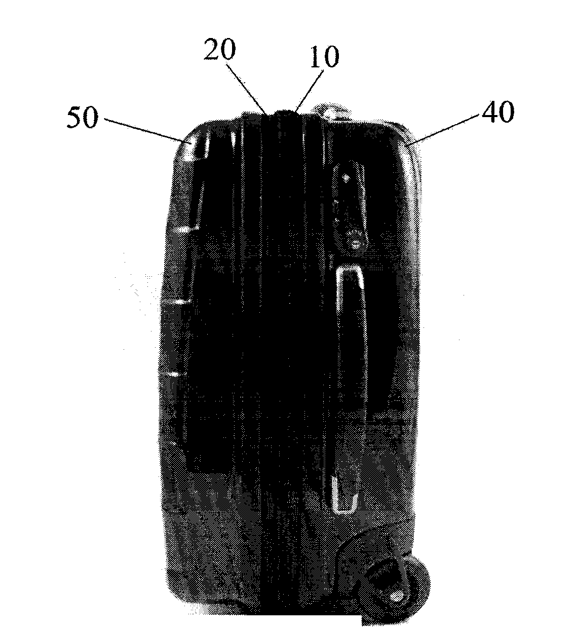
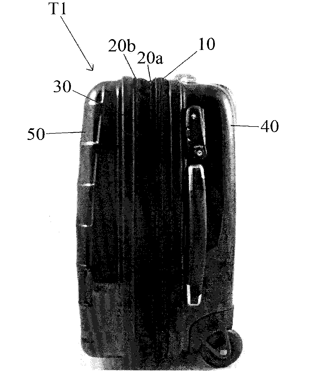
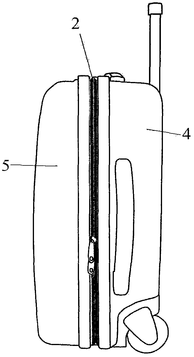
[0041] With reference to these drawings, the trolley case T usually adopts a pair of opposite half-shell structures 4, 5 made of hard materials, and a four-sided reinforcement in the middle is installed between the two half-shell structures. The shroud 3, made of soft material, is used for the connection between the two half-shells themselves 4,5.

[0042] Trolley case of the present invention also has adopted two slide fasteners 1,2 covering all around.

[0043]The first zipper 1 in the above-mentioned zippers is connected with and corresponds to the edges at the peripheral openings of the above-mentioned four-side reinforced girdle 3 located in the middle. That is, the first zipper 1 is used to control the opening and closing of the entire trolley case T, and to widen and expand the structural state of the trolley case, such as Figure 2B and Figure 3B shown.

[0044] On the contrary, the second zipper 2 is used when wanting to keep the above-mentioned two half-shell str...


PUM


Abstract

The present invention relates to an expandable trolley comprising an interfaced pair of preferably rigid semi-bodies, between which a perimeter band of soft material is mounted and closed by a corresponding perimeter zipper; it being provided that said trolley is provided on the outside of said soft intermediate band with a basically perimeter second zipper, the toothed sides of which are mounted on the interfaced borders of said semi-bodies.

Description

technical field [0001] The invention relates to a retractable and expandable travel trolley case. Background technique [0002] At present, the use range of the trolley case is very wide. It has a vertical shape structure, and is also equipped with one or two pairs of wheels that can slide on the ground, and an extended traction handle. [0003] Despite their widespread use, there are still increasing demands placed on this type of luggage, namely that its dimensions need to be limited. [0004] The above problems are actually mentioned in many places, whether it is in the family, when people need to store a suitcase that is not in use temporarily, or in the "use process", such as when you need to put the suitcase in the cargo hold, or Put luggage on the luggage rack on the plane, or put it in the trunk of the car, or put it on the luggage rack of the train. [0005] In fact, it should be said that there have been trolley cases produced for these specific needs before, tha...

Claims


Application Information

Patent Timeline
IPC IPC(8): A45C7/00
CPCA45C7/0027A45C5/14A45C13/103A45C7/0068
Inventor A·迪贝拉尔迪诺
Owner DIELLE MFR
Why Eureka
Try Eureka