Shear wave elastrography method and apparatus for imaging an anisotropic medium

a shear wave and anisotropic technology, applied in the field of shear wave elastography methods and apparatuses for imaging anisotropic media, can solve the problems of unsatisfactory reproducibility and reliability of images and measurements, giving non-reliable and non-reproducible measurements and images, etc., to improve the quality, reliability and reproducibility of images.

Active Publication Date: 2018-01-04
SUPER SONIC IMAGINE
View PDF8 Cites 8 Cited by
  • Summary
  • Abstract
  • Description
  • Claims
  • Application Information

AI Technical Summary

Benefits of technology

[0055]With these features, the shear wave characteristics and in particular the wave front and the propagation direction of the shear wave can be determined on the basis of the spatial characteristics of the anisotropic medium. This strongly improves the quality, reliability and reproducibility of the images and measurement obtained by shear wave elastography and imaging.

Problems solved by technology

While the method of U.S. Pat. No. 7,252,004 gives full satisfaction when the viscoelastic medium is homogeneous, the reproducibility and reliability of images and measurements is not optimal when the viscoelastic medium is an anisotropic medium containing fibers.
Unfortunately, shear wave propagates differently in anisotropic medium containing fibers compared to homogeneous medium since their propagation parameters depend not only of the physical characteristics of the medium but also of the relative angle of the shear wave front with fibers directions.
Thus, depending on the relative angle of the shear wave propagation direction with fibers directions, the measured value of the propagation parameters of the shear wave can vary and gives non reliable and non reproducible measurements and images to the shear wave elastography.

Method used


Image

  • Shear wave elastrography method and apparatus for imaging an anisotropic medium
  • Shear wave elastrography method and apparatus for imaging an anisotropic medium
  • Shear wave elastrography method and apparatus for imaging an anisotropic medium

Examples


first embodiment

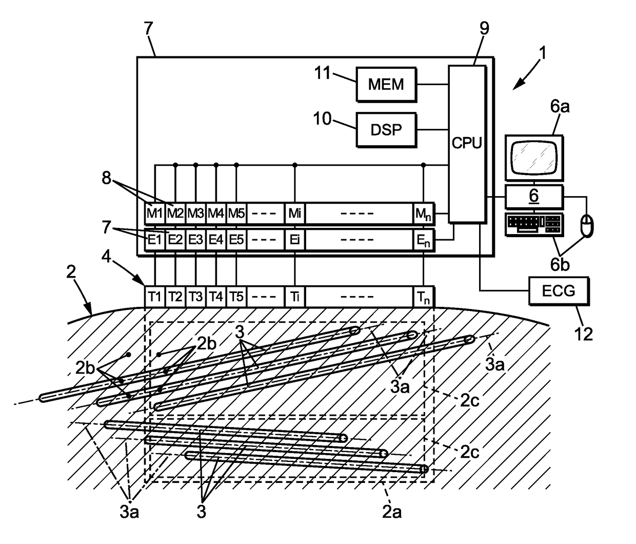
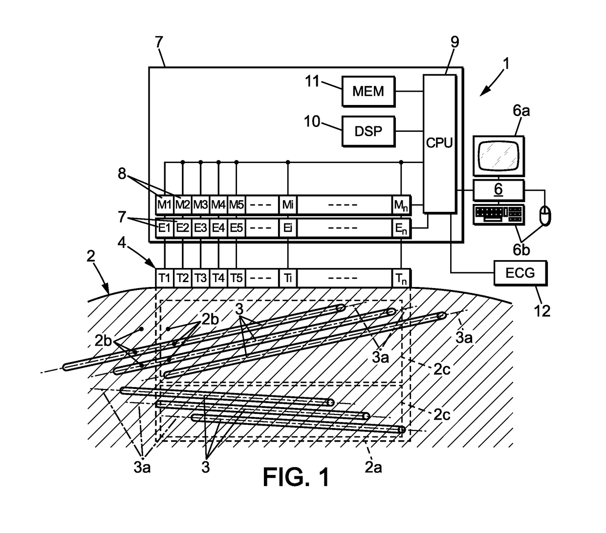
[0151]In a first embodiment, the initial physical parameter is acquired using B-mode ultrasonic imaging. The initial physical parameter can be, in particular, an image of the region of interest 2c in the anisotropic medium 2.

[0152]To this aim, the control system 6, 9 can perform a conventional B-mode ultrasound image of the observation field 2a using the transducer array 4 in a standard ultrasound way. Standard ultrasound imaging consists of an insonification of the medium with a cylindrical wave that focuses on a given point. Using the backscattered echoes of this single insonification, a complete line of the image is computed using a dynamic receive beamforming process.

second embodiment

[0153]In the invention, the initial physical parameter is acquired using shear wave elastography or imaging.

[0154]In this second embodiment, the initial physical parameter can be a shear wave propagation parameter or an image obtained by shear wave imaging.

[0155]The control system 6, 9 may in particular acquire the image by performing a shear wave elastography or imaging similar to the shear wave imaging step c) described here-before.

[0156]Thus, the initial ultrasonic acquisition step may comprises a shear wave imaging step comprising:

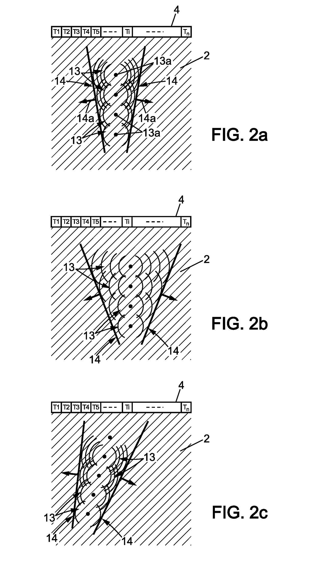
[0157]a1) an excitation substep during which a shear wave is generated inside the anisotropic medium with a shear wave direction; and

[0158]a2) an observation substep during which the propagation of said shear wave is observed simultaneously at a multitude of points in the at least one region of interest to acquire an initial physical parameter.

[0159]Advantageously, the initial imaging step a), can comprise the acquisition of several initial physical pa...

third embodiment

[0172]In a third embodiment, of the invention, the initial physical parameters are shear wave propagation parameters and the spatial characterization step b) may also be performed automatically as follow.

[0173]In this embodiment, the initial ultrasonic acquisition step a) may advantageously comprise a plurality of shear wave imaging steps associated with a plurality of shear wave directions and with a plurality of initial physical parameter acquired in at least one region of interest in the observation field in the anisotropic medium.

[0174]More precisely, each shear wave imaging step is performed substantially as described here before in relation with shear wave imaging step c). Thus, each shear wave imaging step comprises first an excitation substep a1) during which a shear wave is generated inside the anisotropic medium with an associated shear wave direction of the plurality of shear wave directions. Thus several shear waves are generated having distinct shear wave directions.

[01...


PUM


Abstract

A shear wave elastography method for imaging an observation field in an anisotropic medium, including an initial ultrasonic acquisition step during which initial physical parameters are acquired in at least one region of interest; a spatial characterization step during which a set of spatial characteristics of the anisotropic medium is determined on the basis of the initial physical parameter; an excitation substep during which an shear wave is generated inside the anisotropic medium on the basis of the set of spatial characteristics; and an observation substep during which the propagation of the shear wave is observed simultaneously at a multitude of points in the observation field.

Description

FIELD OF THE INVENTION[0001]The present invention relates to imaging methods and apparatuses using shear waves, more precisely to shear wave elastography method and apparatuses for imaging anisotropic media.BACKGROUND OF THE INVENTION[0002]U.S. Pat. No. 7,252,004 describes an example of a shear wave elastography method for imaging a viscoelastic medium. While the method of U.S. Pat. No. 7,252,004 gives full satisfaction when the viscoelastic medium is homogeneous, the reproducibility and reliability of images and measurements is not optimal when the viscoelastic medium is an anisotropic medium containing fibers.[0003]In fact, measurements and images obtained with shear wave elastography are computed from the observed displacement and / or deformation of the viscoelastic medium submitted to a shear wave.[0004]Unfortunately, shear wave propagates differently in anisotropic medium containing fibers compared to homogeneous medium since their propagation parameters depend not only of the p...

Claims


Application Information

Patent Timeline
Patent Type & Authority Applications(United States)
IPC IPC(8): A61B8/08A61B8/00G01S7/52G01S15/89
CPCA61B8/485A61B8/5207A61B8/463G01S7/52042G01S15/8918A61B8/085G01S15/8915G01S7/52022
Inventor BERCOFF, JEREMYHENRY, JEAN-PIERRE
Owner SUPER SONIC IMAGINE
Why Eureka
Try Eureka