

Golf club
- Summary
- Abstract
- Description
- Claims
- Application Information
AI Technical Summary
Benefits of technology
Problems solved by technology
Method used
Image

Examples
example 1
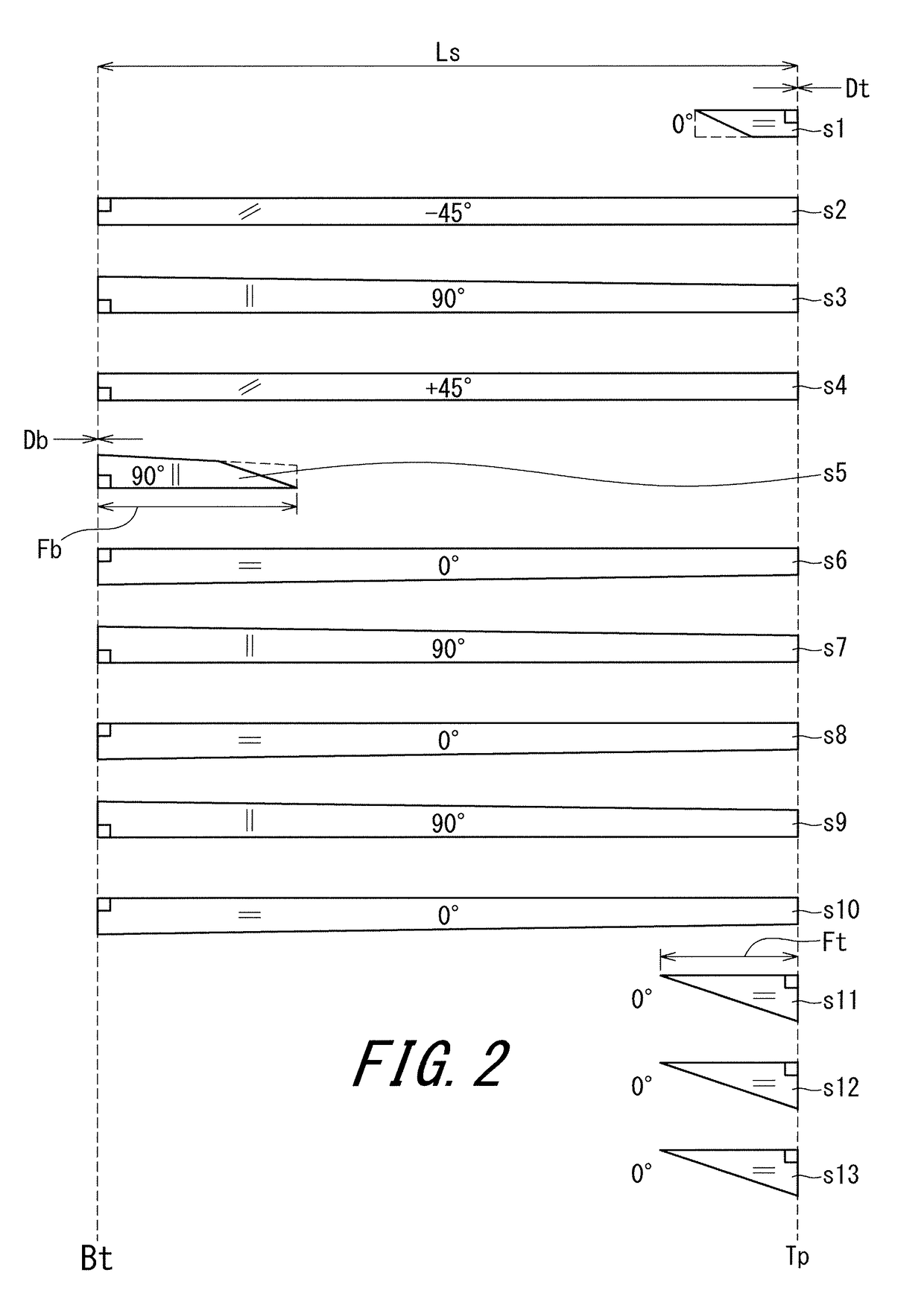
[0148]A shaft having the laminated constitution shown in FIG. 2 was produced. The shaft of Example 1 was obtained in the same manner as in the manufacturing process of the shaft 6. Specifications were adjusted by using the above described design items. Prepregs used for the sheets were as follows. The axial-direction length Fb of the butt partial hoop layer s5 was 270 mm.[0149]Sheet s1: A glass fiber reinforced prepreg (having a fiber elastic modulus of 7 tf / mm2)[0150]Sheet s2: A carbon fiber reinforced prepreg (having a fiber elastic modulus of 40 tf / mm2)[0151]Sheet s3: A carbon fiber reinforced prepreg (having a fiber elastic modulus of 30 tf / mm2)[0152]Sheet s4: A carbon fiber reinforced prepreg (having a fiber elastic modulus of 40 tf / mm2)[0153]Sheet s5: A carbon fiber reinforced prepreg (having a fiber elastic modulus of 24 tf / mm2)[0154]Sheet s6: A carbon fiber reinforced prepreg (having a fiber elastic modulus of 24 tf / mm2)[0155]Sheet s7: A carbon fiber reinforced prepreg (havi...
example 2
[0163]The shaft of Example 2 was obtained in the same manner as in Example 1 except that the laminated constitution shown in FIG. 3 was adopted. Ten EI values of Example 2 are shown in Table 4 below.
[0164]In Example 2, prepregs used for the sheets were as follows.[0165]Sheet s1: A glass fiber reinforced prepreg (having a fiber elastic modulus of 7 tf / mm2)[0166]Sheet s2: A carbon fiber reinforced prepreg (having a fiber elastic modulus of 40 tf / mm2)[0167]Sheet s3: A carbon fiber reinforced prepreg (having a fiber elastic modulus of 40 tf / mm2)[0168]Sheet s4: A carbon fiber reinforced prepreg (having a fiber elastic modulus of 24 tf / mm2)[0169]Sheet s5: A carbon fiber reinforced prepreg (having a fiber elastic modulus of 24 tf / mm2)[0170]Sheet s6: A carbon fiber reinforced prepreg (having a fiber elastic modulus of 24 tf / mm2)[0171]Sheet s7: A carbon fiber reinforced prepreg (having a fiber elastic modulus of 30 tf / mm2)[0172]Sheet s8: A carbon fiber reinforced prepreg (having a fiber elas...
example 3
[0178]The shaft of Example 3 was obtained in the same manner as in Example 1 except that the laminated constitution shown in FIG. 4 was adopted. Ten EI values of Example 3 are shown in Table 5 below.
[0179]In Example 3, prepregs used for the sheets were as follows.[0180]Sheet s1: A glass fiber reinforced prepreg (having a fiber elastic modulus of 7 tf / mm2)[0181]Sheet s2: A carbon fiber reinforced prepreg (having a fiber elastic modulus of 40 tf / mm2)[0182]Sheet s3: A carbon fiber reinforced prepreg (having a fiber elastic modulus of 30 tf / mm2)[0183]Sheet s4: A carbon fiber reinforced prepreg (having a fiber elastic modulus of 40 tf / mm2)[0184]Sheet s5: A carbon fiber reinforced prepreg (having a fiber elastic modulus of 24 tf / mm2)[0185]Sheet s6: A carbon fiber reinforced prepreg (having a fiber elastic modulus of 24 tf / mm2)[0186]Sheet s7: A carbon fiber reinforced prepreg (having a fiber elastic modulus of 30 tf / mm2)[0187]Sheet s8: A carbon fiber reinforced prepreg (having a fiber elas...
PUM
 Abstract
Description
Claims
Application Information