Image forming apparatus

Active Publication Date: 2018-01-04
CANON KK
View PDF2 Cites 1 Cited by
  • Summary
  • Abstract
  • Description
  • Claims
  • Application Information

AI Technical Summary

Benefits of technology

[0006]The present disclosure is directed to an image forming apparatus capable of reducing occurrence of image defect by

Problems solved by technology

However, according to the technique described in Japanese Patent Application Laid-Open No. 2013-130709, although the moisture content of the transfer material can be acquired, it is difficult to reduce image defect when water droplets are adhered to a fixing unit due to dew condensation.
If water droplets are adhered to the fixing unit when a tone

Method used


Image

  • Image forming apparatus
  • Image forming apparatus
  • Image forming apparatus

Examples


Example

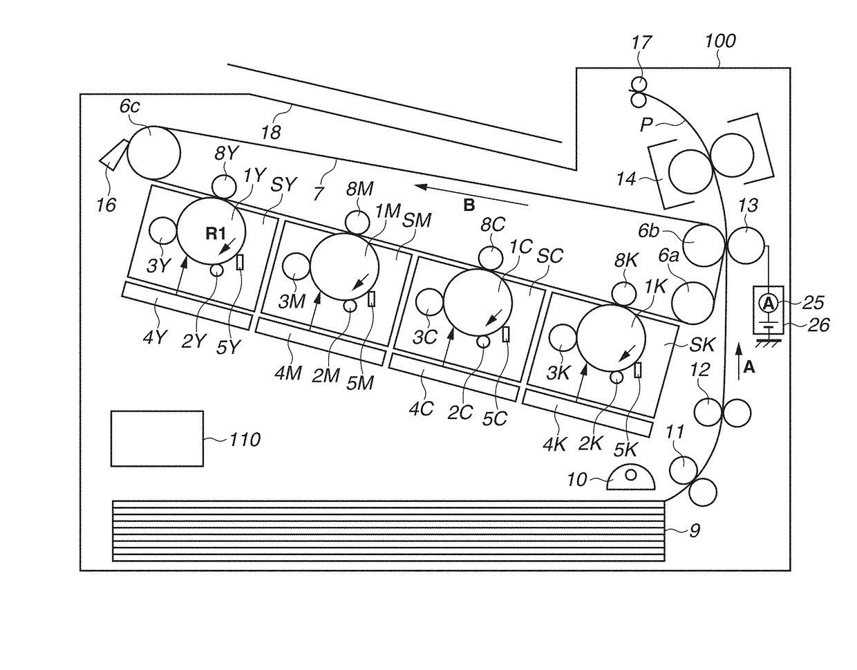
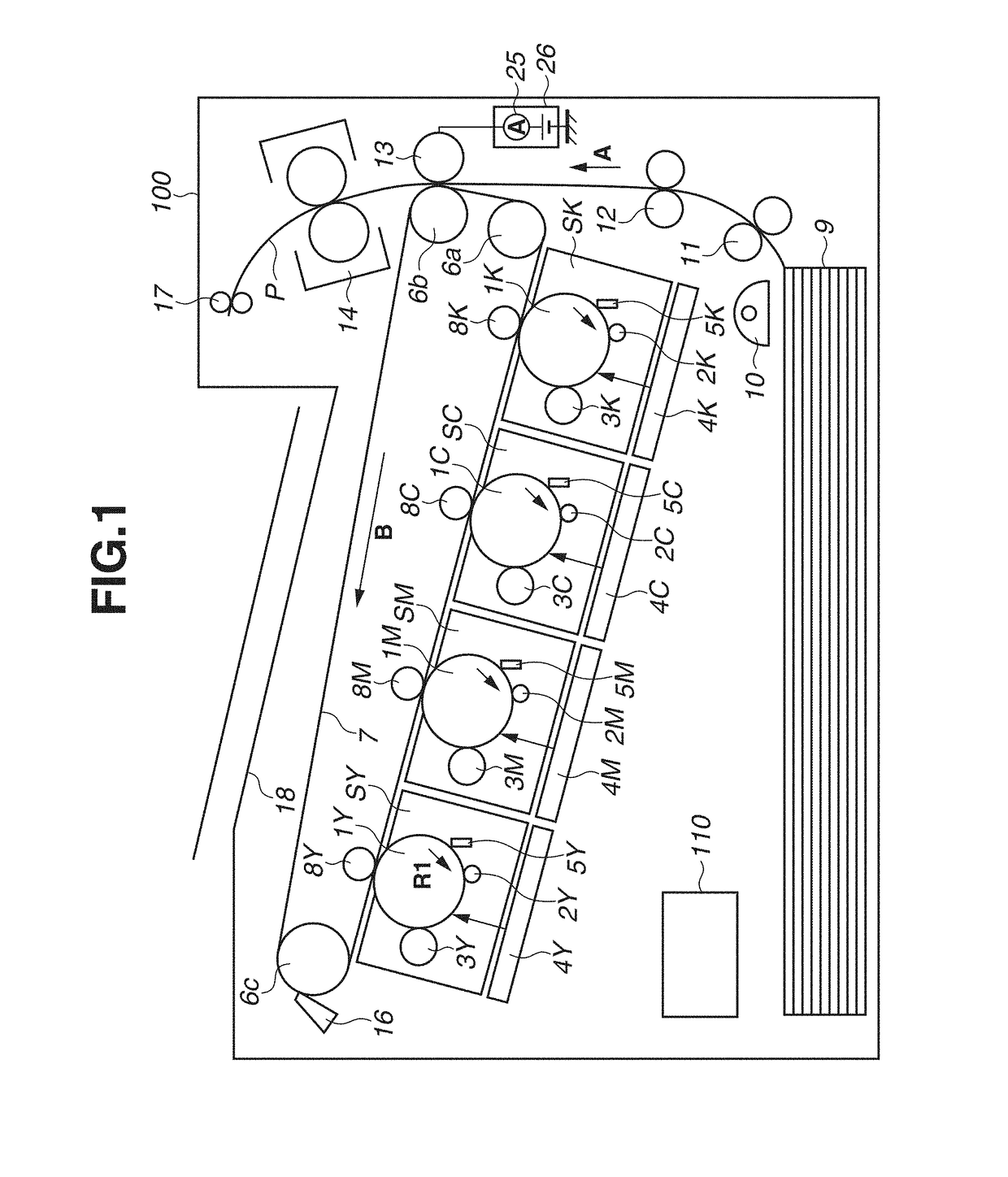
[0066]In the first embodiment, in step S102, before the transfer material P reaches the secondary transfer portion, the predetermined voltage V0 is applied to the secondary transfer roller 13 from the transfer power source 26, and the reference current value I0a flowing in the secondary transfer roller 13 is detected by the detection circuit 25. On the other hand, as illustrated in FIGS. 6 and 7, in a second embodiment, a configuration in which a reference current value I0b is detected after the transfer material P reaches the secondary transfer portion in step S203 will be described. A configuration described in the present embodiment is similar to that of the first embodiment except for a point in which the reference current value I0b is detected after the transfer material P reaches the secondary transfer portion in step S203, so that the same reference numerals are applied to the units common to those described in the first embodiment, and description thereof will be omitted.

[00...


PUM


Abstract

An image forming apparatus includes an image bearing member, a transfer member, a power source, a detection unit, and a fixing unit. The transfer member transfers a toner image to a transfer material from the image bearing member. The detection unit detects electric current flowing in the transfer member when the power source applies voltage to the transfer member. The fixing unit fixes a toner image to a transfer material by heat. The heat to the fixing unit is controlled where a subsequent. transfer material conveyance stops after the transfer material is discharged from the fixing unit, in a case where a second current value, detected when voltage is applied to the transfer member contacting the fixing unit and the transfer member, is greater than a first current value detected. when voltage is applied to the transfer member before the transfer material reaches the fixing unit.

Description

BACKGROUND OF THE INVENTIONField of the Invention[0001]The present disclosure relates to an image forming apparatus such as a copying machine or a printer employing an electrophotographic method.Description of the Related Art[0002]In an image forming apparatus employing an electrophotographic method, a toner image borne by an image bearing member is electrostatically transferred to a transfer material such as a sheet of paper or anoverhead projector (OHP) sheet by applying voltage to the transfer member arranged to face the image bearing member such as a drum-shape photosensitive member (hereinafter, referred to as “photosensitive drum”) or an intermediate transfer member. Thereafter, the transfer material to which the toner image has been transferred is conveyed to a fixing unit, and the fixing unit applies heat and pressure to the transfer material to fix the toner image thereon.[0003]An amount of moisture contained in a transfer material varies according to an environment where t...

Claims


Application Information

Patent Timeline
IPC IPC(8): G03G15/00G03G15/20G03G15/02G03G21/08G03G21/20
CPCG03G15/80G03G15/2075G03G15/2089G03G15/0283G03G21/206G03G21/08G03G15/2021G03G15/2039G03G15/6564G03G21/203G03G15/1675G03G15/2025G03G15/206G03G15/5037G03G15/657G03G21/20
Inventor OHNO, MASARUWATANABE, KENJIKUME, TAKAOHIRAJIMA, MAREHIKO
Owner CANON KK
Why Eureka
Try Eureka