Optical scanning device
- Summary
- Abstract
- Description
- Claims
- Application Information
AI Technical Summary
Benefits of technology
Problems solved by technology
Method used
Image
Examples
first embodiment
[0090](Overall Structure)
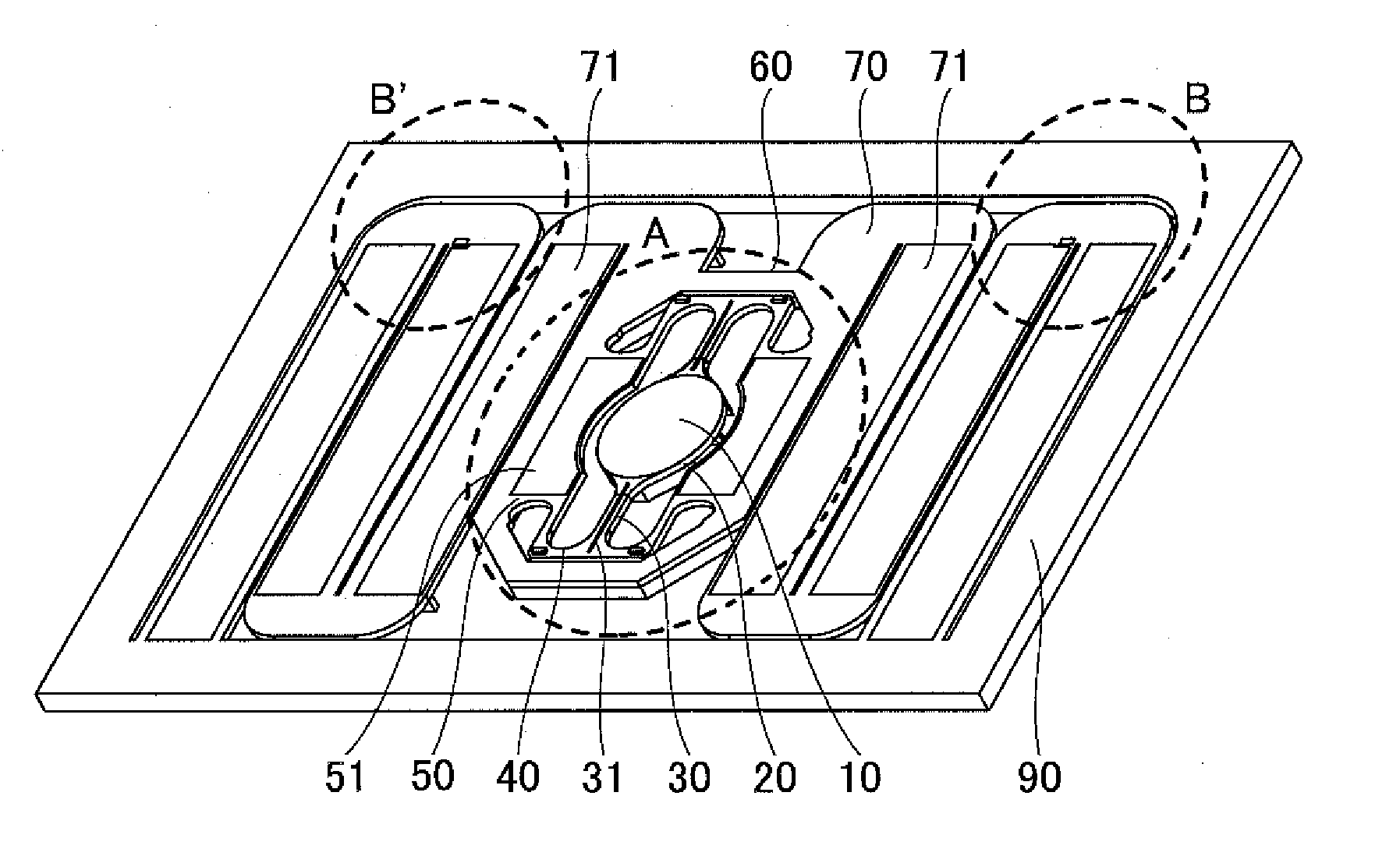
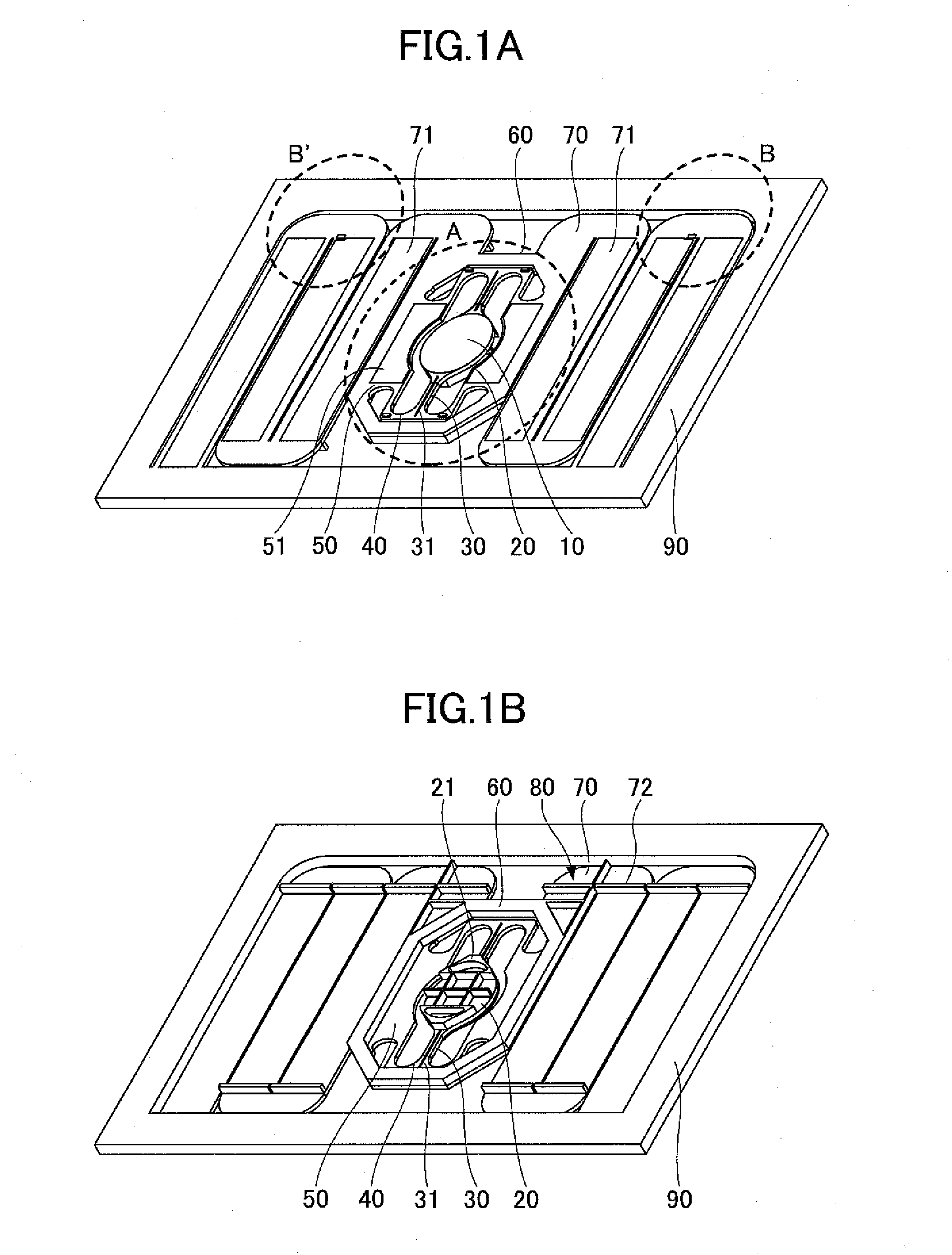
[0091]FIGS. 1A and 1B are perspective views showing an example of a configuration of an optical scanning device of a first embodiment of the present invention. FIG. 1A is a top perspective view showing an example of the optical scanning device of the first embodiment. FIG. 1B is a bottom perspective view showing an example of the optical scanning device of the first embodiment.
[0092]In FIGS. 1A and 1B, the optical scanning device of the present invention includes a mirror 10, a mirror supporting part 20, torsion beams 30, coupling beams 40, first drive beams 50, a movable frame 60, second drive beams 70, crosstalk preventing ribs 80, and a fixed frame 90. The torsion beams 30 include a slit 31. Moreover, as shown in FIG. 1A, the first drive beams 50 include a drive source 51, and the second drive beams 70 include a drive source 71. Furthermore, as shown in FIG. 1B, a rib is provided on the back side of the mirror supporting part 20, and harmonic superpositio...
first example
[0115]FIGS. 6A and 6B are views showing performance results of an optical scanning device of a first example. FIG. 6A is a view showing performance results of an optical scanning device of a comparative example without the slit 31. FIG. 6B is a view showing performance results of an optical scanning device of the first example with the slit 31.
[0116]FIG. 6A shows moments in a case where the optical scanning device of the comparative example is displaced linearly and nonlinearly. FIG. 6A shows if the moments between the linearity and the nonlinearity disagree, the nonlinearity is intense, and if the moments between the linearity and the nonlinearity agree, the nonlinearity does not occur. In FIG. 6A, the moments of the linearity and the nonlinearity do not overlap, the optical scanning device of the comparative example including the torsion beams 130 without the slits 31 shows a characteristic with intense nonlinearity.
[0117]On the other hand, FIG. 6B shows moments in a case where th...
second example
[0146]FIGS. 15A through 15D are views showing a configuration and performance results of an optical scanning device of a second example. FIG. 15A is a view showing a cross-sectional configuration of a torsion beam 30 of the optical scanning device of the second example. As shown in FIG. 15A, a slit 31 is provided in the center of a torsion beam 30, and torsion beams 30L, 30R having a cross-sectional shape similar to a square on both sides of the slit 31. The left torsion beam 30L and the right torsion beam 30R have the same cross-sectional configuration, and the width is expressed as W, and the thickness is expressed as T.
[0147]FIG. 15B is a view showing a plane configuration on the back side of the optical scanning device of the second example. As shown in FIG. 15B, the optical scanning device of the second example has a configuration similar to the optical scanning device of the first embodiment described in FIGS. 13A and 13B. Specifically, the optical scanning device of the secon...
PUM
 Abstract
Description
Claims
Application Information
 - R&D
- Intellectual Property
- Life Sciences
- Materials
- Tech Scout
- Unparalleled Data Quality
- Higher Quality Content
- 60% Fewer Hallucinations
Browse by: Latest US Patents, China's latest patents, Technical Efficacy Thesaurus, Application Domain, Technology Topic, Popular Technical Reports.
© 2025 PatSnap. All rights reserved.Legal|Privacy policy|Modern Slavery Act Transparency Statement|Sitemap|About US| Contact US: help@patsnap.com


