Electroplating bath containing wetting agent for defect reduction

a technology of wetting agent and electrodelating bath, which is applied in the direction of basic electric elements, semiconductor/solid-state device manufacturing, electric apparatus, etc., can solve the problems of voids, pits, craters, and new device-killing defects in the electroplating layer, and improve the appearance of deposits. , the effect of reducing the pit defects of the electroplating layer

Inactive Publication Date: 2007-06-19
NOVELLUS SYSTEMS
View PDF10 Cites 55 Cited by
  • Summary
  • Abstract
  • Description
  • Claims
  • Application Information

AI Technical Summary

Benefits of technology

[0017]The present invention helps to solve some of the problems outlined above by providing an electroplating solution that contains a wetting agent in addition to a suppressor and an accelerator. A plating solution in accordance with the invention improves wetting of a wafer substrate surface, thereby reducing pit defects in electroplated metal. Compared with conventional electroplating solutions, the combination of a wetting agent with a suppressor functions to achieve improved deposit appearance, desired levels of current suppression on a wafer surface, a reduction of plating-bath contact angle on a substrate surface, a reduction of solid-liquid surface tension, and a reduction in the formation of micelles or polymer agglomerates.

Problems solved by technology

Prior art electroplating techniques are susceptible to thickness irregularities.
While the problem of increasing deposition rate with radius exists for all wafers, it is exacerbated in the case of larger wafers.
The implementation of new process flows has caused new device-killing defect formation.
Critical post-plating in-film killer defects in electroplated copper layers include pits, craters, and voids, which typically form during the electroplating process or during the post-plate anneal steps.
The presence of additives and chloride ions in an electrolytic plating bath, however, often leads to occlusion of undesired material in the deposited metal layer.
Pit defects often result in void formation in vias and trenches and subsequent yield loss.

Method used


Image

  • Electroplating bath containing wetting agent for defect reduction
  • Electroplating bath containing wetting agent for defect reduction
  • Electroplating bath containing wetting agent for defect reduction

Examples


example 1

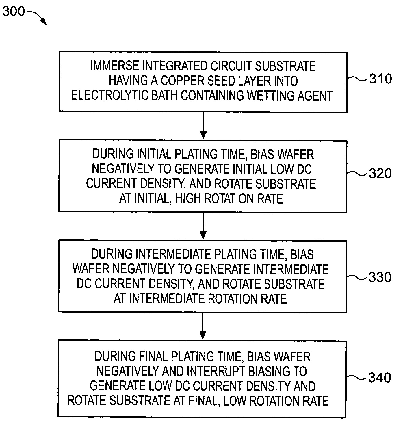
[0050]A Novellus Model SABRE® xT apparatus was used to electroplate copper on integrated circuit substrate wafers using various electroplating solutions containing different amounts of BASF PLURONIC® P104 (“P104”) wetting agent. Copper was electroplated on a series of 200 mm silicon wafers having a PVD copper seed layer with a thickness of approximately 100 nm. Process specifications of a standard SABRE® xT copper DC electrofill process are known in the art.

[0051]Each of five plating solutions contained: 40 g / l of dissolved copper metal, added as copper sulfate pentahydrate (CuSO4·5H2O); 10 g / l H2SO4; 50 mg / l chloride ion, added as HCl; 6 ml / l VIAFORM® accelerator; 2.5 ml / l VIAFORM® leveler; and 2 ml / l VIAFORM® suppressor. In addition, the five different plating solutions comprised a concentration of P104 corresponding to 0, 10, 50, 80, and 100 ppm, respectively. The VIAFORM® accelerator, suppressor, and leveler are commercially available from Enthone Company. PLURONIC® P104 is comm...

example 2

[0056]The effectiveness of plating solutions in accordance with the invention in reducing lines of pits on wafers was studied. Three different plating solutions having compositions similar to those in Example 1 were prepared, except that the concentrations of P104 were 0, 100 and 200 ppm, respectively. A series of 200 mm silicon wafers having a PVD copper seed layer with a thickness of approximately 100 nm were etched with 10% sulfuric acid solution prior to electroplating. The etching with sulfuric acid, and other similar etching techniques, typically creates lines of pit defects under conventional operating conditions. Each of the three plating solutions was used to deposit copper on three different wafers, so that copper was electroplated on a total of nine wafers. Electroplating conditions and techniques essentially identical to those used in Example 1 were utilized.

[0057]After electroplating, the wafers were examined for defects using KLA Tencor AIT II metrology tool and visual...

example 3

[0058]The impact of using a plating solution in accordance with the invention on trench-filling ability was evaluated. A conventional plating solution having a composition similar to those in Example 1 had a composition of 0 ppm P104. A plating solution in accordance with the invention contained 200 ppm P104. A series of 200 mm silicon wafers were prepared to contain trenches having a width of either 0.2 μm or 0.3 μm and an aspect ratio of approximately 4 and 2.7, respectively. A PVD copper seed layer with a thickness of approximately 100 covered the surfaces of each wafer. Each of the two plating solutions was used to deposit copper on a wafer having a 0.2 μm or 0.3 μm trenches. Electroplating conditions and techniques essentially identical to those used in Example 1 were utilized. No degradation of electroplating trench-filling performance was observed on any of the wafers on which copper was deposited using the plating solution in accordance with the invention.


PUM

PropertyMeasurementUnit
concentrationaaaaaaaaaa
cloud-point temperatureaaaaaaaaaa

Abstract

An electroplating solution contains a wetting agent in addition to a suppressor and an accelerator. In some embodiments, the solution has a cloud point temperature greater than 35° C. to avoid precipitation of wetting agent or other solute out of the plating solution. In some embodiments, the wetting agent decreases the air-liquid surface tension of the electroplating solution to 60 dyne/cm2 or less to increase the wetting ability of the solution with a substrate surface. In some embodiments of a method for plating metal onto substrate surface, the electroplating solution has a measured contact angle with the substrate surface less than 60 degrees.

Description

FIELD OF THE INVENTION[0001]The present invention pertains to the field of electroplating of integrated circuit substrate wafers, particularly to electroplating solutions having improved wetting ability to decrease defects in plated metal.BACKGROUND OF THE INVENTION[0002]Integrated circuits are formed on wafers by well-known processes and materials. These processes typically include the deposition of thin film layers by sputtering, metal-organic decomposition, chemical vapor deposition, plasma vapor deposition, and other techniques. These layers are processed by a variety of well-known etching technologies and subsequent deposition steps to provide a completed integrated circuit.[0003]A crucial component of integrated circuits is the wiring or metallization layer that interconnects the individual circuits. Conventional metal deposition techniques include physical vapor deposition, e.g., sputtering and evaporation, and chemical vapor deposition techniques. Some integrated circuit man...

Claims


Application Information

Patent Timeline
Patent Type & Authority Patents(United States)
IPC IPC(8): C25D3/38C25D5/02
CPCC25D3/38C25D5/04C25D5/18C25D5/627
Inventor WEBB, ERIC G.REID, JONATHAN D.SUKAMTO, JOHN H.TAKADA, YUICHI
Owner NOVELLUS SYSTEMS
Why Eureka
Try Eureka