Reduction-drive device

a technology of reduction gears and drive shafts, which is applied in the direction of electric propulsion mounting, gears, transportation and packaging, etc., can solve the problems of easy vibration or abnormal noise in the reduction gears, and achieve the effects of less influence, less vibration or abnormal noise, and improved sound oscillating performance and durability

Inactive Publication Date: 2005-01-13
TOCHIGI FUJI IND CO LTD
View PDF11 Cites 59 Cited by
  • Summary
  • Abstract
  • Description
  • Claims
  • Application Information

AI Technical Summary

Benefits of technology

[0020] It is an object of the invention to accomplish more improve the sound oscillating performance and the durability with less influences by attaching errors of the electric motor, decrease occurrences of vibrations or abnormal noises, and to improve the sound oscillating performance and the durability.

Problems solved by technology

However, there has been a problem that if building such a structure of merely carrying out the high reduction by the first and second reduction mechanisms 1209, 1219, abnormal noises easily occur in the reduction gears 1211, 1215 or the reduction gears 1221, 1223.

Method used


Image

  • Reduction-drive device
  • Reduction-drive device
  • Reduction-drive device

Examples


first embodiment

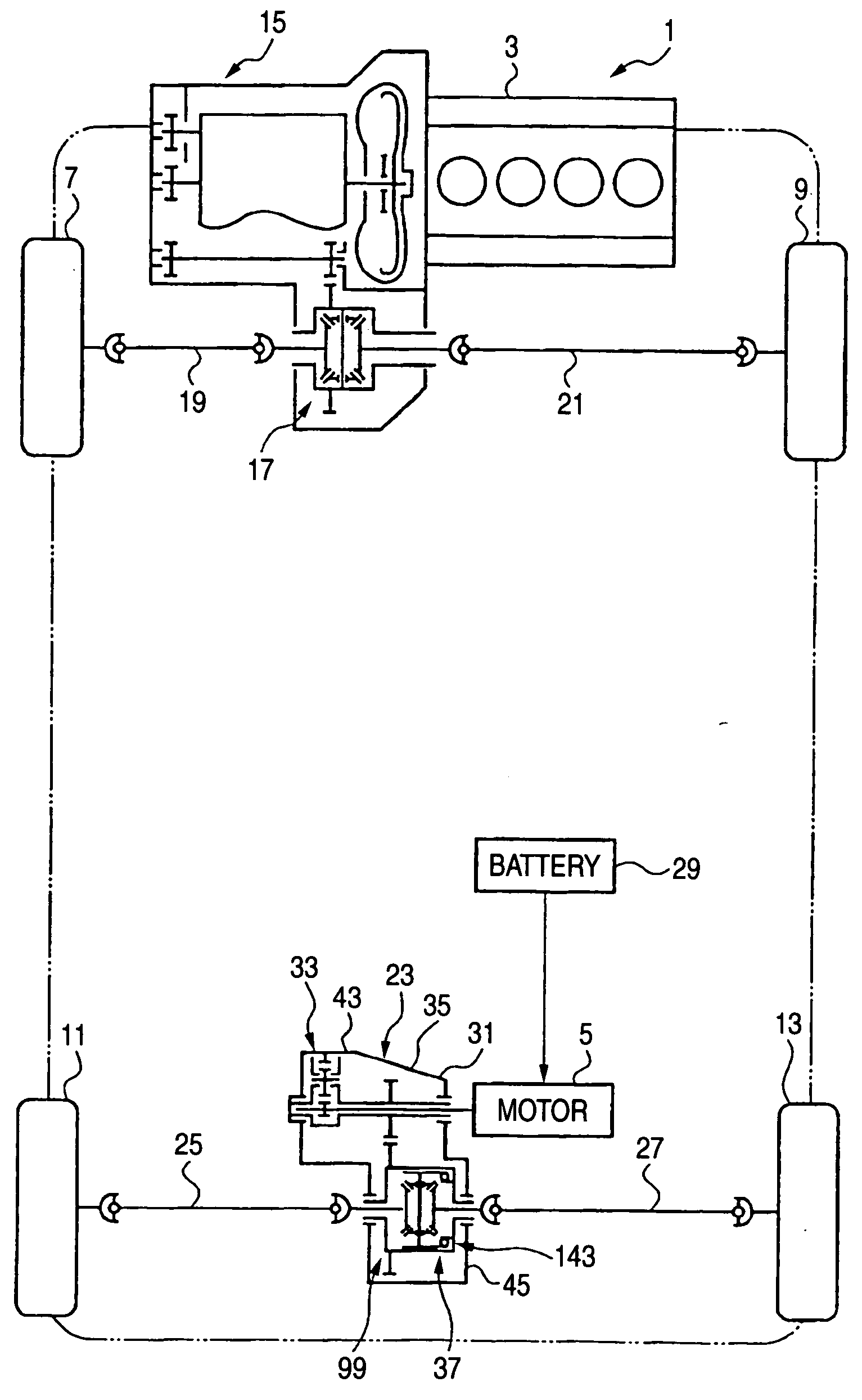
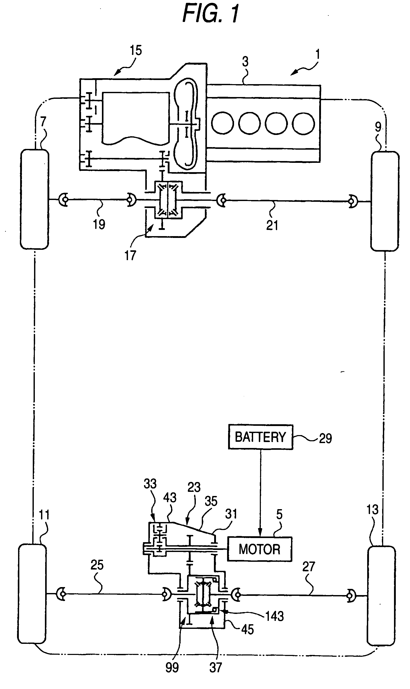
[0068]FIG. 1 is a skeleton plan view of the hybrid automobile applied with the motor reduction-drive device according to the first embodiment of the invention. As seeing FIG. 1, the hybrid automobile 1 has the engine 3 as the main drive source and the electric motor 5 as the sub-drive source. In the first embodiment, the engine 3 is the drive source for driving the left and right front wheels 7, 9, while the electric motor 5 is the drive source for driving the left and right rear wheels 11, 13. It is also possible to drive the front wheels by the electric motor 5 of the sub-drive source, and drive the rear wheels 11, 13 by the engine 3 of the main drive source.

[0069] The output of the engine 3 is issued into a front differential 17 as the differential device via a transmission 15. To the front differential 17, via left and right axle shafts 19, 21, the front wheels 7, 9 are connected in interlocking.

[0070] The output of the electric motor 5 is issued into the motor reduction-drive...

second embodiment

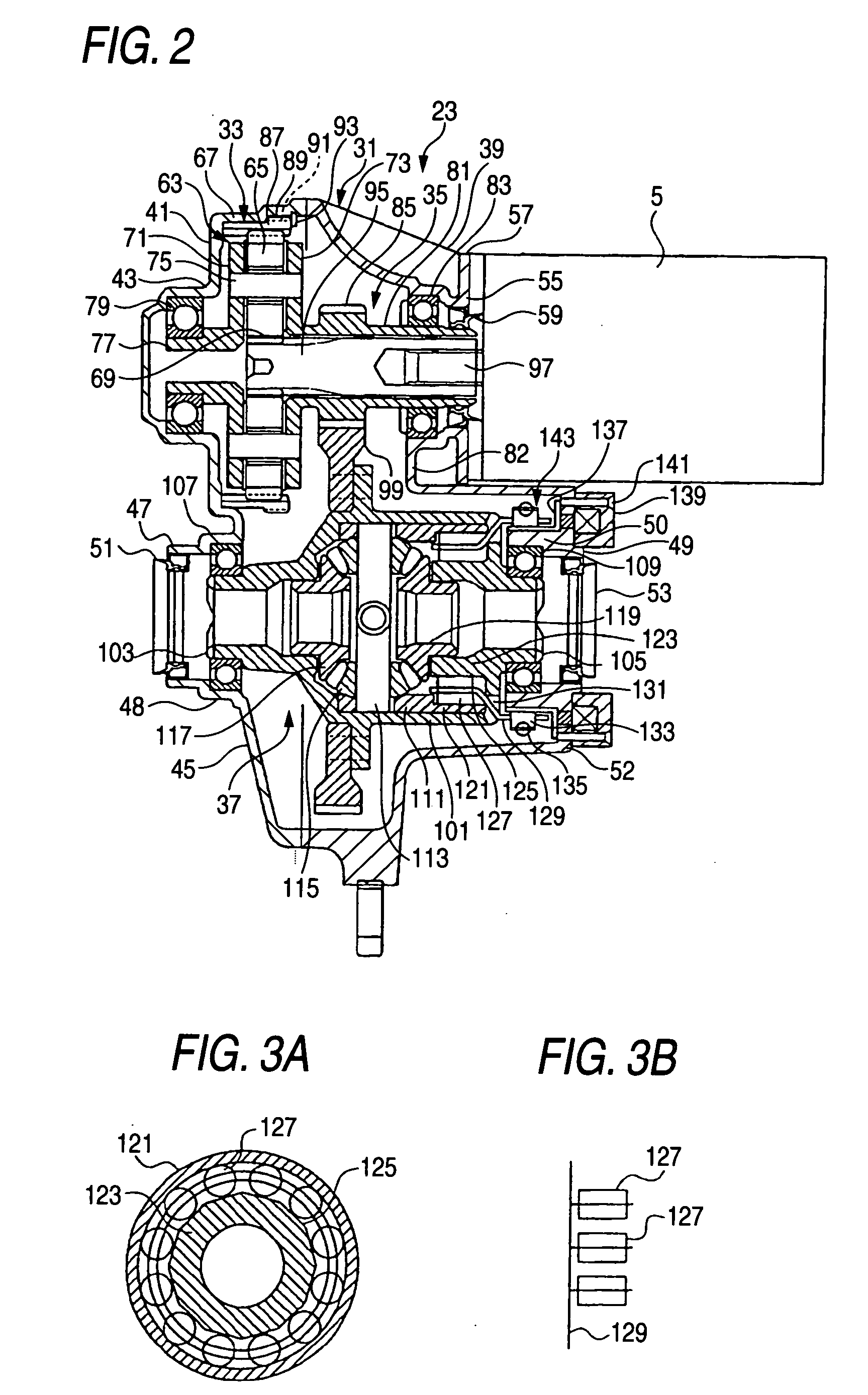
[0119]FIGS. 4, 5A and 5B are concerned with a second embodiment of the invention, and FIG. 4 is a cross sectional view of the motor reduction-drive device, and FIG. 5A is a cross sectional view showing the relation between the connecting part and the engaging part, while FIG. 5B is a simple developing view showing the arrangement of the rollers. By the way, the basic structure is the same as that of the first embodiment, and the corresponding parts are given the same reference numerals for explanation.

[0120] The motor reduction-drive device 23A of the present embodiment modifies the connecting part 121A of the intermittent mechanism 143A and the engaging part 123A. The connecting part 121A of this embodiment is provided integrally with the inner case 111A. The engaging part 123A is provided to the differential case 101A. A polygonal engaging face 125A is formed in the inside of the differential case 101A. The rollers 127 are interposed between the connecting part 121A and the engag...

third embodiment

[0124]FIG. 6 is a skeleton plan view of the four wheel drive automobile applied with the reduction-drive device according to the third embodiment of the invention. As seeing FIG. 6, the four wheel drive automobile 1001 has the engine 1003 being the internal combustion engine as the main drive source and the electric motor 1005 as the sub-drive source being the drive source. In this embodiment, the engine 1003 is the drive source for driving the left and right front wheels 1007, 1009, while the electric motor 1005 is the drive source for driving the left and right rear wheels 1011, 1013. It is also possible to drive the front wheels by the electric motor 1005 of the sub-drive source, and drive the rear wheels 1011, 1013 by the engine 1003 of the main drive source.

[0125] The output of the engine 1003 is issued into a front differential device 1017 as the differential device via a transmission 1015. To the front differential 1017, via left and right axle shafts 1019, 1021, the front w...


PUM


Abstract

A reduction-drive device has a first and a second reduction mechanism and distribution device. The first reduction mechanism has a planetary carrier, a planetary gear rotatably supported by the planetary carrier, an internal gear in mesh with the planetary gear and a sun gear. The first reduction mechanism is supported by the housing so as to reduce driving force of the electric motor. The second reduction mechanism is positioned between the electric motor and the first reduction mechanism so as to reduce an output of the first reduction mechanism. The differential device is supported by the housing so as to distribute the output of the second reduction mechanism to a wheel side.

Description

BACKGROUND OF THE INVENTION [0001] The present invention relates to a reduction-drive device used to such as a four wheel drive automobile. [0002] As a conventional reduction-drive device, there is, for example, a device as shown in FIG. 15. The reduction-drive device 201 of FIG. 15 reduces an output of an electric motor 203 to transmit to left and right axle shafts and drive the left and right rear wheels. The electric motor 203 is served as a sub-drive source, and at a side of front wheels, an engine is served as a main drive source, and the left and right front wheels are driven by the engine. [0003] The motor reduction-drive device 201 rotatably supports a first transmission shaft 207, that receives an output of the electric motor 203, at a housing 205 of a stationary side. The first transmission shaft 207 has a reduction gear 211 composing a first reduction mechanism 209. The reduction gear 211 is in mesh with another reduction gear 213 composing the first reduction mechanism 2...

Claims


Application Information

Patent Timeline
Patent Type & Authority Applications(United States)
IPC IPC(8): B60K6/365B60K6/405B60K6/48F16H1/06F16H1/28F16H48/30
CPCB60K1/00Y10S903/91B60K6/405B60K6/48B60K6/52F16H1/06F16H1/28F16H48/08F16H48/16F16H48/22F16H48/30F16H48/34F16H48/40F16H2048/204F16H2048/346Y02T10/6221Y02T10/6265B60K6/365Y02T10/62
Inventor TERAOKA, MASAO
Owner TOCHIGI FUJI IND CO LTD
Why Eureka
Try Eureka