Apparatus and method for mounting imagers on stress-sensitive polarizing beam splitters

a technology of stress-sensitive polarizing beam splitter and apparatus, which is applied in the field of optical systems, can solve the problems of unsatisfactory polarization rotation on the light path to the imager, reducing the contrast of the projection system, and not environmentally desirable materials, so as to reduce the occurrence of thermally and mechanically induced birefringence

Inactive Publication Date: 2006-11-23
3M INNOVATIVE PROPERTIES CO
View PDF13 Cites 53 Cited by
  • Summary
  • Abstract
  • Description
  • Claims
  • Application Information

AI Technical Summary

Benefits of technology

[0007] The invention generally relates to optical systems that use optical elements such as polarizing beamsplitters (PBSs), and related aspects of mounting the PBS in the optical system. An important aspect of the invention relates to mounting of the optical element (e.g., PBS) in the optical system via the exit prism (e.g., optically less sensitive component of the PBS) rather than the input prism (e.g., optically highly sensitive component of the PBS). By isolating the input prism from mechanical connection, the occurrence of thermally and mechanically induced birefringence can be reduced.

Problems solved by technology

When used in a liquid crystal on silicon (LCoS) type imager, undesirable rotation of the polarization can occur both on the light path to the imager and on the light path after being reflected by the imager.
Rotation of the light both entering and exiting the imager can cause undesirable light to leak through the polarizing layer thereby reducing contrast of the projection system.
Such glasses contain lead (chemical symbol Pb) in significant quantities and therefore are not environmentally desirable materials.
These materials can also be expensive and difficult to process.
Additionally, the low SOC glasses have a high refractive index, in excess of 1.8, which may lead to optical inefficiencies or aberrations when matching to the lower refractive index polarizing layers.
Without the use of lead in the PBS, the PBS can be highly sensitive to mechanical stresses that result in birefringence and other performance degrading issues.

Method used


Image

  • Apparatus and method for mounting imagers on stress-sensitive polarizing beam splitters
  • Apparatus and method for mounting imagers on stress-sensitive polarizing beam splitters
  • Apparatus and method for mounting imagers on stress-sensitive polarizing beam splitters

Examples


Embodiment Construction

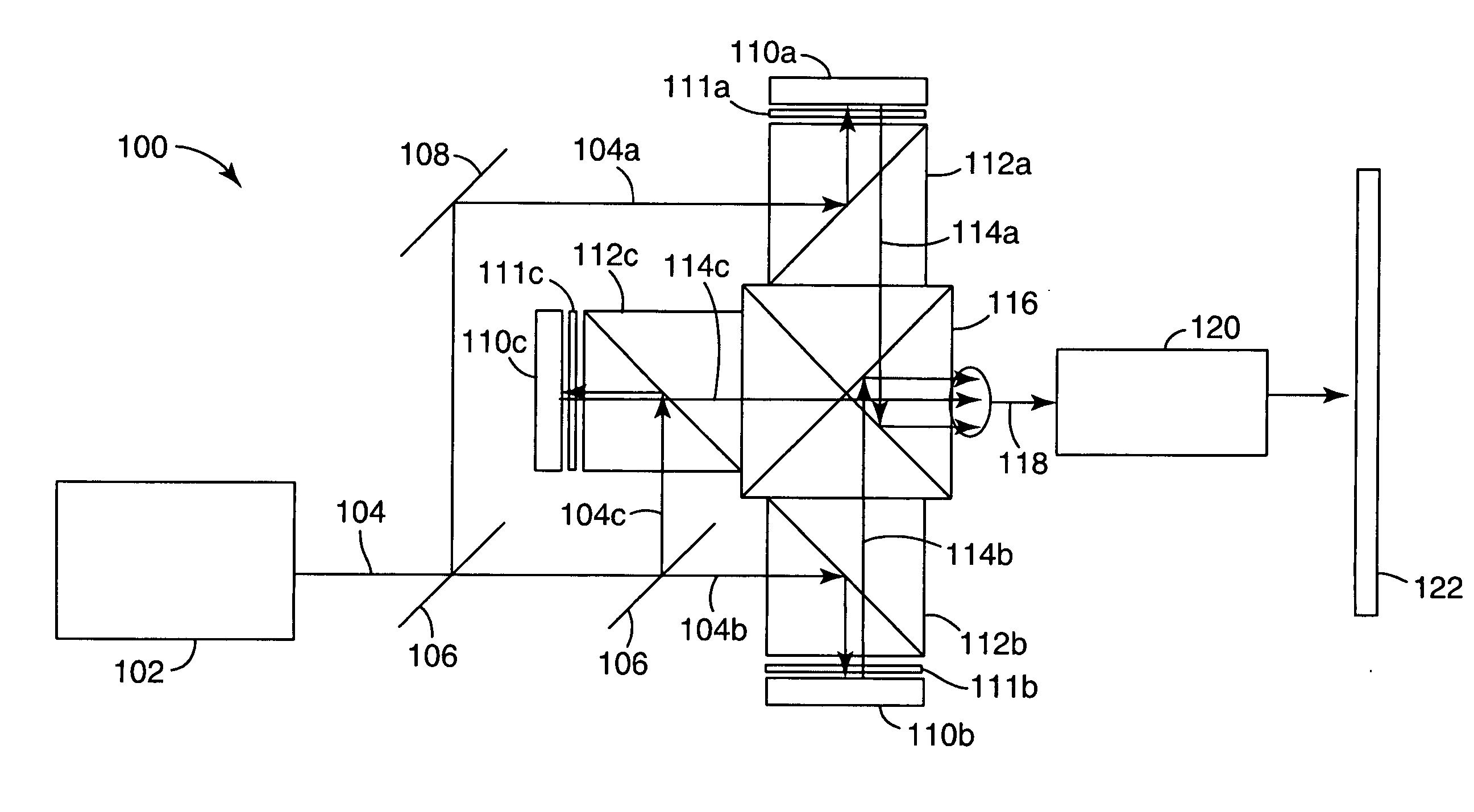
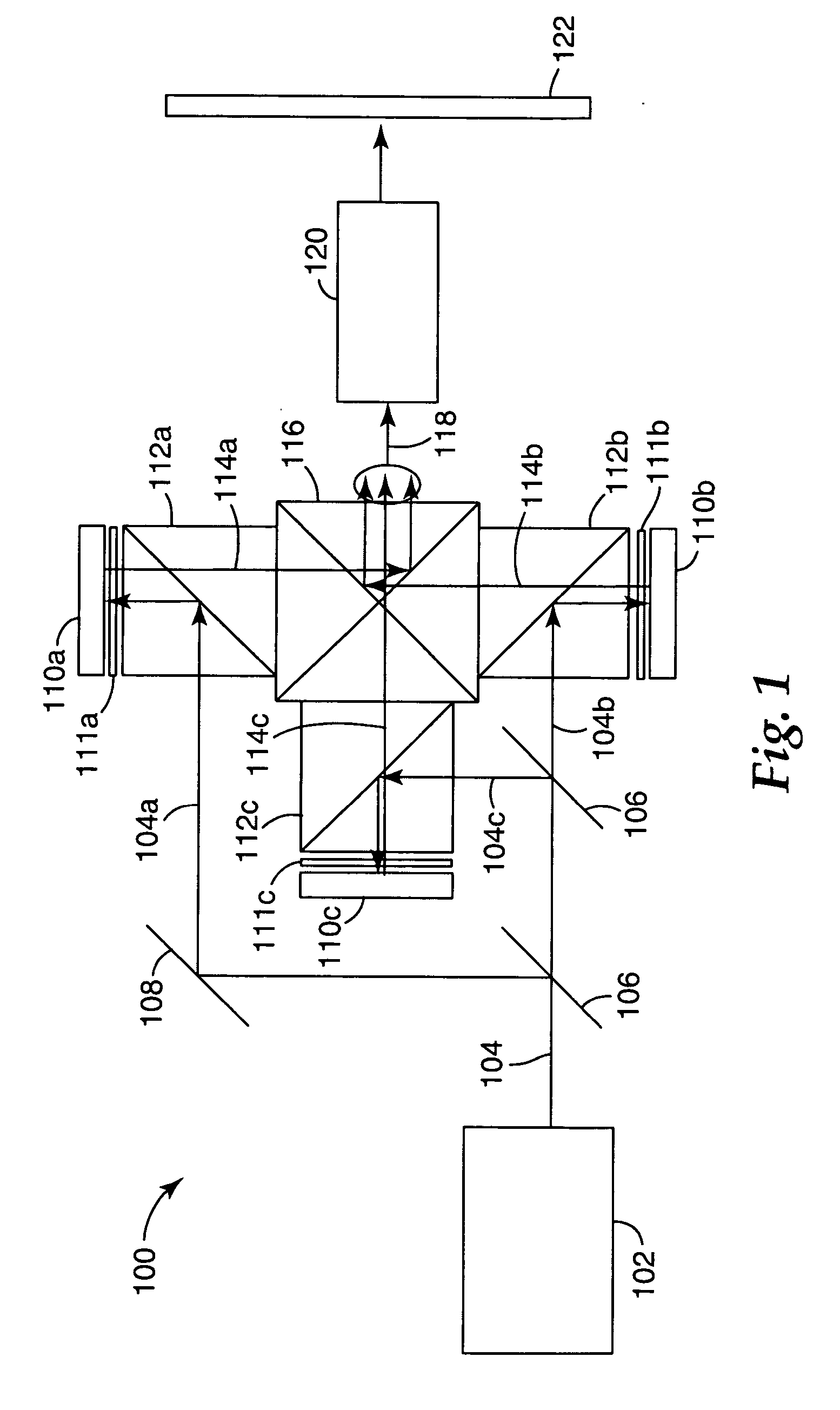
[0027] The present invention is applicable to systems that use optical devices such as polarizing beamsplitters (PBSs). The invention is believed to be particularly useful for image projection systems that incorporate PBSs for separating image light generated using a polarization modulator from illumination light. While the invention may be useful in any application where a PBS is used, it is described below particularly as used in projection systems. The scope of the invention is not intended to be limited to only projection systems. Some specific system wherein the optical devices of the invention are used include televisions, rear projection display devices, a front projection display devices, heads-up displays, head-mounted displays, and wearable displays.

[0028] A PBS is an optical component that splits incident light rays into a first polarization component (e.g., reflected component for MOF polarizers and transmitted component for wire grid polarizers) and a second polarizati...


PUM


Abstract

An optical device that includes an optical element, an imager, and a prism bracket. The optical element includes an optical element having first and second prisms coupled together. The imager is arranged adjacent to the first prism and configured to receive light from or to transmit light to the optical element, wherein the first prism is spaced between the second prism and the first imager. The prism bracket is coupled between the second prism and the first imager to hold the first imager in a desired positional alignment relative to the optical element. The optical device may further include additional sets of an optical element, imager, and prism bracket, wherein all of the sets are coupled to a color light combiner.

Description

FIELD OF THE INVENTION [0001] The invention relates to optical systems and more particularly to optical systems that use polarizing beamsplitters (PBSs), and related aspects of mounting the PBS in the optical system. BACKGROUND [0002] The function of a polarizing beamsplitter (PBS) is to reflect light in one polarization state and to transmit light in the orthogonal polarization state. Consequently, PBSs find widespread use in optical systems that rely on the polarization of the light. An example of one such system is an image projection system that uses a reflective liquid crystal display (LCD) panel for modulating an illumination light beam: a polarized illumination light beam is directed to the LCD panel, for example by reflection in the PBS. The light beam is spatially modulated by the LCD panel so that the reflected beam contains some unmodulated light in the polarization state of the illumination beam and some modulated light in the orthogonal polarization state. The unmodulat...

Claims


Application Information

Patent Timeline
Patent Type & Authority Applications(United States)
IPC IPC(8): G03B21/14
CPCG03B21/14H04N9/317H04N9/3144G03B21/2073
Inventor DOMROESE, MICHAEL K.KEYES, MICHAEL P.MA, JIAYING
Owner 3M INNOVATIVE PROPERTIES CO
Why Eureka
Try Eureka