Wireless laser system for power transmission utilizing a gain medium between retroreflectors

a laser system and gain medium technology, applied in the direction of lasers, transmission, biochemical equipment and processes, etc., can solve the problems of limiting the detection capability of the system, affecting the safety of spillover power, and power may be dissipated in a way

Active Publication Date: 2013-09-03
WI CHARGE
View PDF61 Cites 20 Cited by
  • Summary
  • Abstract
  • Description
  • Claims
  • Application Information

AI Technical Summary

Benefits of technology

[0011]The transmitter and receiver should mutually operate safely and with sufficient efficiency that they can provide effective power for mobile electronic devices within their area of reach, regardless of the position and orientation of those devices. The safety and efficiency effects are related, since both are ultimately dependent on the effectiveness with which power dissipation in directions other than in the intended beam, is controlled.
[0041]Such a system may further include at least one adaptive optical element for modifying the properties of the lasing system such that stable resonator modes are obtained. The at least one adaptive optical element may be such as to reduce the diameter of the laser beam impinging on the gain medium, thereby increasing the overlap between the laser beam and the gain medium. In any of the above systems, at least one of the adaptive optical element and the gain medium should have sufficiently low birefringence that the generation of spurious birefracted beams is significantly reduced.
[0045]Additionally, in such a free-space lasing system with an adaptive optical element, the overlap may be maximized by adjusting the focusing power of the adaptive optical element, such that the laser beam does not experience significant additional angular shift as a result of the focusing power adjustment. Such an adaptive optical element may be located adjacent to either the first or the second retroreflector.

Problems solved by technology

Power can be dissipated from the system in a number of ways other than as intended through the output coupler:(a) When the resonator is operating outside of its stability zone, as an unstable resonator, the nature of the modes generated are such that power may be dissipated in a way that limits the capability of the system to detect, by measuring power and or beam shape, if such a beam has become partially blocked.
Thus, if a person were to position himself inadvertently in the line of sight of the small “spill-over” power of the unstable resonator mode, i.e. that part of the power not reflected back into the resonator, then not only may this spill-over power be unsafe, but its blocking by the person would have no effect on the laser power or the mode shape, and could not thus be detected by monitoring the laser power or mode.
This makes it difficult to stop the radiation in time to prevent potential damage to the surroundings.
Mechanisms will be described to detect if such a portion of the beam is emitted in a different direction to that intended.(c) If the beam intensity at any point exceeds the damage threshold of the components at that point, unpredictable behavior and even failure of this component may happen and power may leak out.
This lasing would create a power leak in the system that may significantly reduce power transmission efficiency, and would probably be unsafe.
This makes it difficult to use conventional optics in the beam path, as its position is unknown.
On the other hand, without additional cooling, which would be inconvenient and an additional expense, photovoltaic cells are today still incapable of handling the power densities generated, which could reach 1W on a surface area of 1 mm2.

Method used


Image

  • Wireless laser system for power transmission utilizing a gain medium between retroreflectors
  • Wireless laser system for power transmission utilizing a gain medium between retroreflectors
  • Wireless laser system for power transmission utilizing a gain medium between retroreflectors

Examples


Embodiment Construction

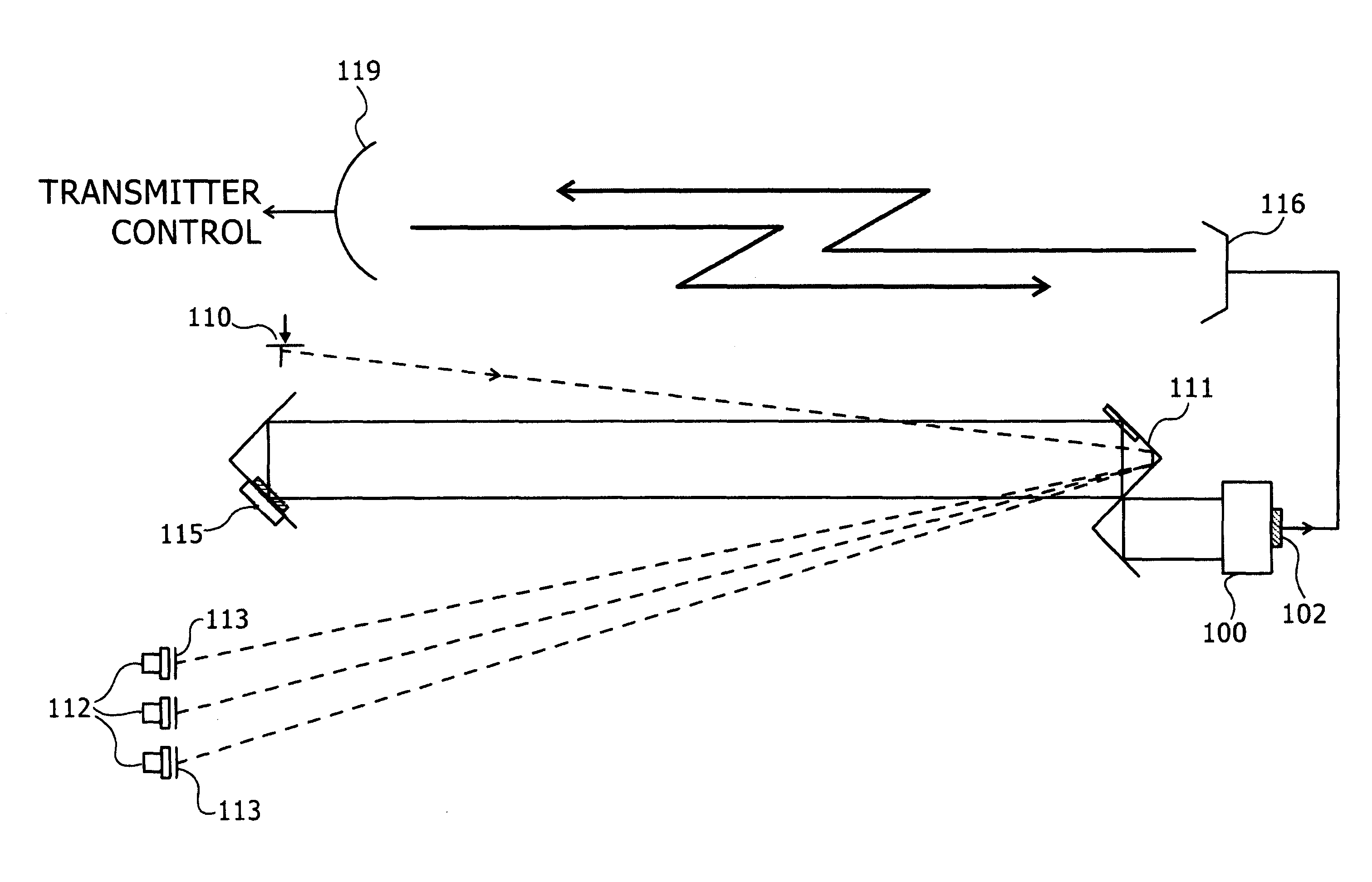
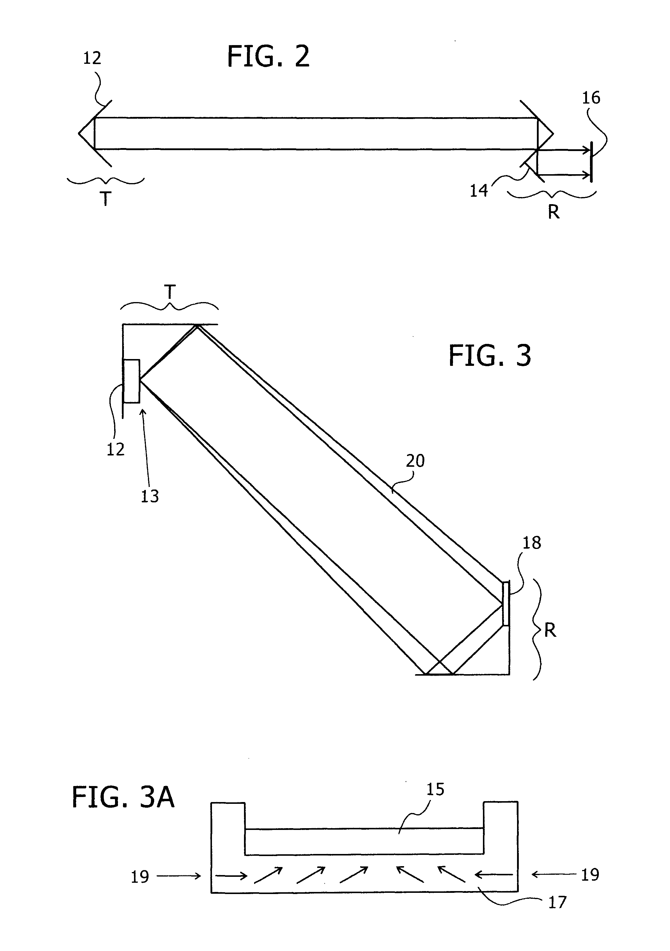
[0090]Reference is now made to FIG. 2, which illustrates schematically an exemplary power transmitting system comprising an electrically powered transmitter T, and a receiver R, which allows extraction of electric energy, in order to power, for instance, a mobile electronic device. The transmitter should be mounted at a safe location out of reach of possible human contact, such as on the ceiling of a room or connected to a lighting fitting. The position should be such that the transmitter has a line of sight to as much of the room's volume as possible. Suitable positions may be to embed the transmitter within a ceiling lamp, within a television set or within a speaker unit, one approach to achieve that would be to add a standard lamp connection to the transmitter so that it can connect to a standard lamp fitting.

[0091]T and R form a laser resonator, in which significant power circulates in the form of a laser beam(s), which may advantageously be in the infra-red. Since this arrangem...


PUM

PropertyMeasurementUnit
field of viewaaaaaaaaaa
surface areaaaaaaaaaaa

Abstract

An optical power beam transmission systems, with a directional light transmitter and receiver. The transmitter contains an amplifying laser medium, and this together with a retroreflector in the receiver, forms a laser resonator. When lasing sets in, the receiver can extract optical power through an output coupler and convert it to electrical power. The gain medium may be a disc having a thickness substantially smaller than its lateral dimensions. The laser resonator is operated as a stable resonator to ensure safe operation. This is achieved by use of an adaptive optical element, for reducing the diameter of the energy beam impinging on the gain medium, thereby increasing the overlap between the energy beam and the gain medium. As the transmitter-receiver distance is changed, such as by movement of the receiver, the adaptive optical element focal length changes to ensure that the cavity remains within its stability zone.

Description

CROSS-REFERENCE TO RELATED APPLICATIONS[0001]This application is a U.S. National Phase Application under 35 U.S.C. 371 of PCT International Application No. PCT / IL2009 / 000010, which has an international filing date of Jan. 4, 2009, and which claims priority benefit from U.S. Provisional Patent Application No. 61 / 006,255, filed Jan. 3, 2008, the contents of which are incorporated herein by reference in their entirety.FIELD OF THE INVENTION[0002]The present invention relates to the field of the wireless transmission of power to a remote device over free space, especially by means of a laser-like system.BACKGROUND OF THE INVENTION[0003]In recent years mobile devices have found widespread popular use. In many cases, these devices use a battery to provide electric power; in other cases they draw their power from another device such as a computer via an electrical cable, through a USB port for example. One of the most common drawbacks of such devices is the need for recharging the battery,...

Claims


Application Information

Patent Timeline
Patent Type & Authority Patents(United States)
IPC IPC(8): H01J3/14G06M7/00H04B10/00
CPCH01S3/083H04B10/807H01S5/10H04B10/114H01S5/041H01S5/14H01S3/0805H01S3/08072H01S3/0941H01S5/183H01S3/0604H01S3/08059H01S3/1307H01S3/005H04B2001/0416H02J50/30
Inventor ALPERT, ORTALPASCHOTTA, RUDIGER
Owner WI CHARGE
Why Eureka
Try Eureka