Eye tracking illumination

a technology of automatic determination and eye tracking, applied in the field of automatic determination and tracking, can solve the problems of high energy consumption, energy consumption and heat dissipation, and the problem of standard computer output interfaces, and achieve the effect of reliable automatic eye tracking and power efficient and robus

Active Publication Date: 2010-03-18
TOBII TECH AB
View PDF2 Cites 105 Cited by
  • Summary
  • Abstract
  • Description
  • Claims
  • Application Information

AI Technical Summary

Benefits of technology

[0005]The object of the present invention is therefore to provide a power efficient and robust solution, which solves the above pr

Problems solved by technology

This, in turn, results in comparatively high energy consumption.
The energy consumption and the heat dissipation is two-fold problematic.
Namely, due to the high power requirements, standard computer output interfaces (e.g. of USB format (USB—Universal Serial Bus)) cannot normally be used to supply power to the

Method used


Image

  • Eye tracking illumination
  • Eye tracking illumination
  • Eye tracking illumination

Examples


first embodiment

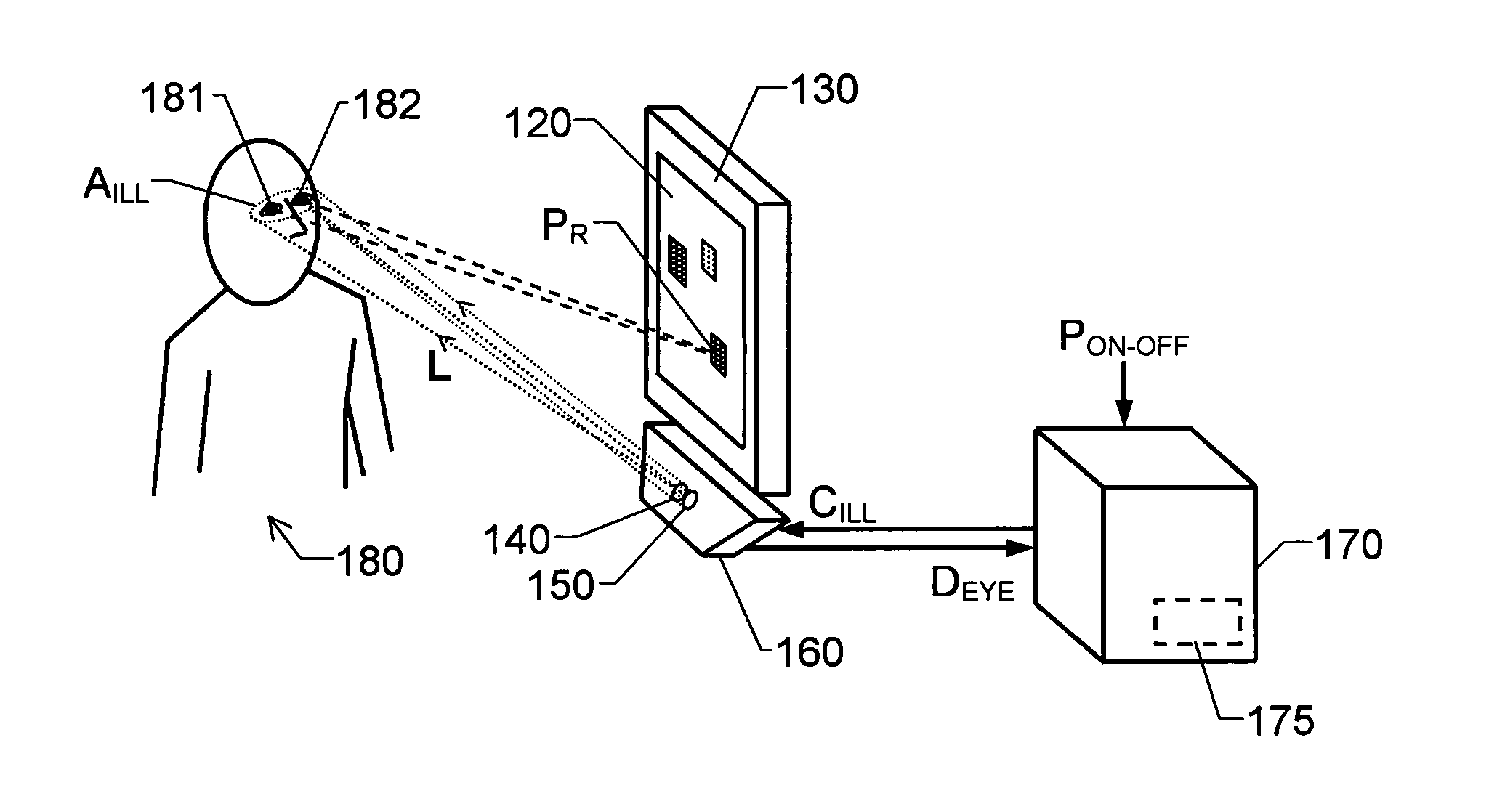
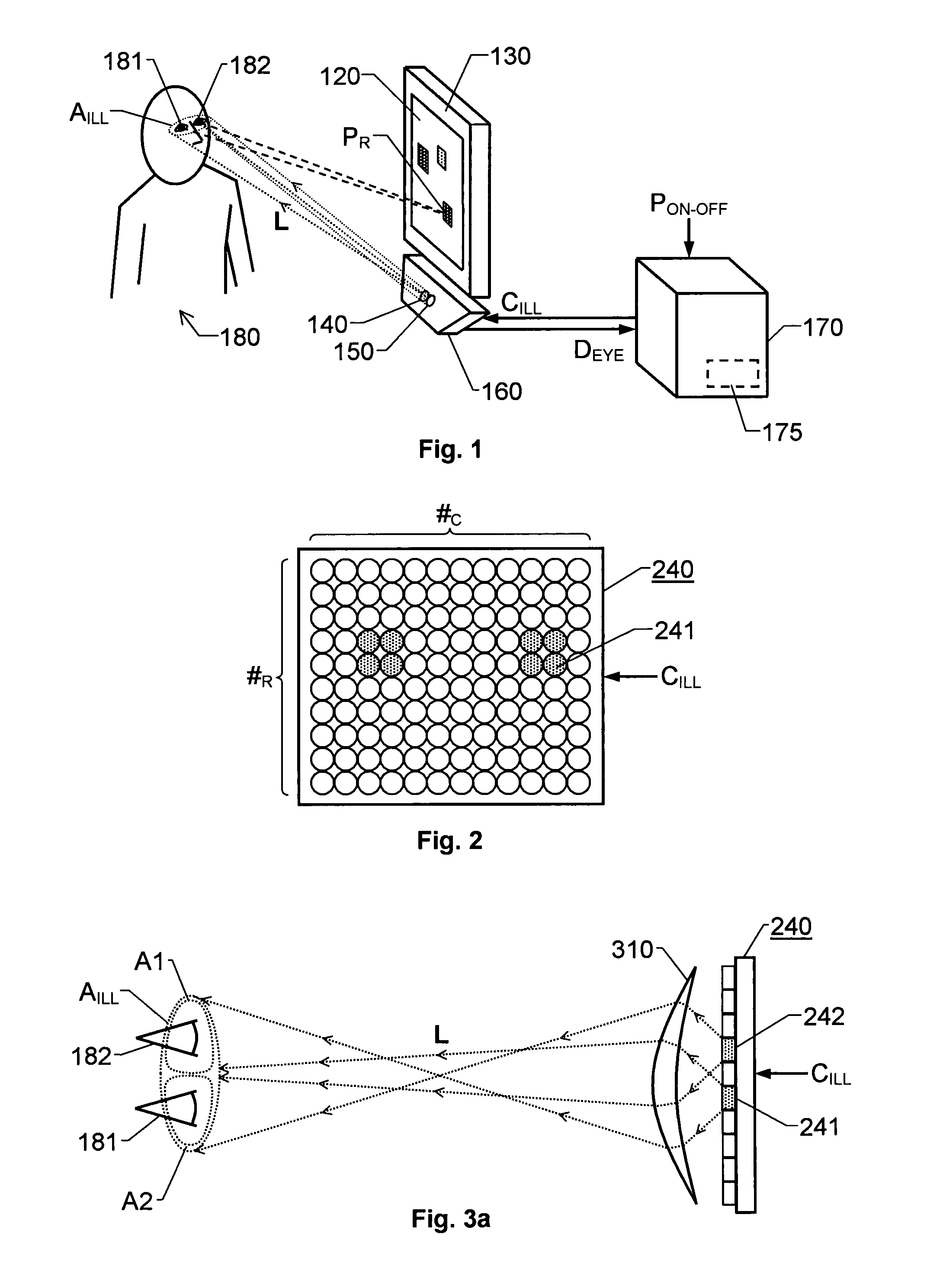
[0034]FIG. 3a illustrates a configuration of light emitting elements 241, 242 in an array 240 of a light source according to the invention. In this embodiment, the light source includes a collimating lens element 310, which is mounted in front of the array 240 (i.e. between the light emitting elements 241, 242 and the intended illumination area AILL). The lens element 310 is adapted to influence light L emitted from the elements 241 and 242 such that an intended area AILL is illuminated, i.e. an area AILL including a respective position estimate of the at least one eye 181 and 182 of a subject 180. Specifically, the collimating lens element 310 is adapted to influence the light L, such that light emitted from a first element 241 is directed towards a first sub-portion A1 of the illumination area AILL. Analogously, light emitted from a second element 242 is directed towards a second sub-portion A2 of the illumination area AILL. Hence, the elements 241 and 242 jointly illuminate the a...

second embodiment

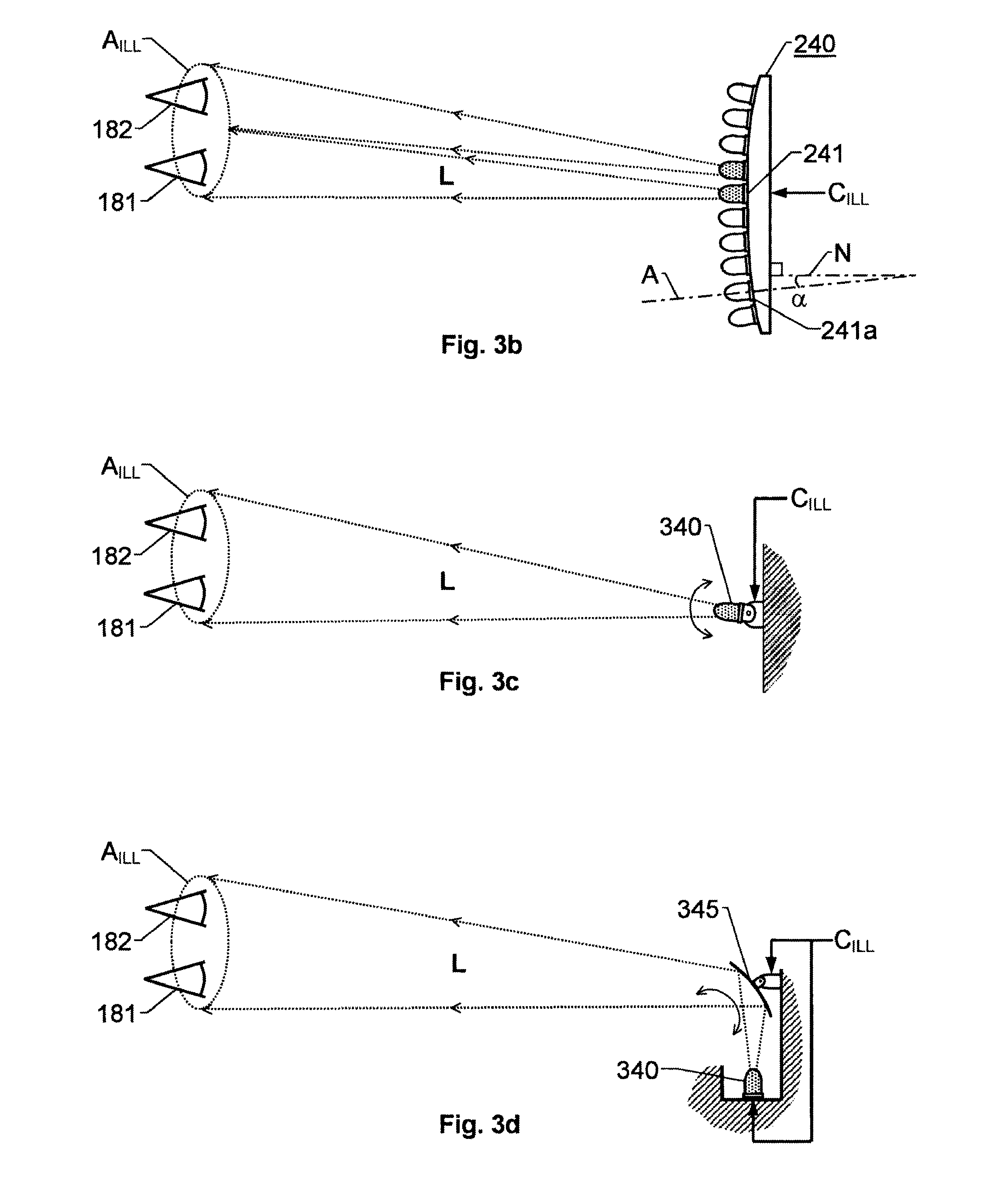
[0037]FIG. 3b illustrates a configuration of light emitting elements 241, 241a in an array 240 of a light source according to the invention. Here, the light emitting element may be organized in essentially the same manner as in FIG. 3a, for instance in rows and columns, or concentrically. However, in the embodiment illustrated in FIG. 3b, the light emitting elements are arranged with different orientations relative to one another. This means that a first element 241a has a first principal light emitting axis A with a first angle a in a first dimension towards a normal plane N of the array 240. A second element 241, however, has a second principal light emitting axis whose angle towards the normal plane N is different from the first angle α at least in the first dimension. Consequently, provided that the first and second light emitting elements 241a and 241 have essentially identical optical properties, these element will emit light in different directions with respect to the first d...


PUM


Abstract

The invention relates to automatic eye tracking, wherein at least one imaging device (150) registers sequential image data (DEYE) representing at least one eye (181; 182) of a subject (180). A processing unit (170) receives the image data (DEYE), and based thereon, produces a position estimate of the at least one eye (181; 182). The processing unit (170) also produces a control signal (DILL)>which is received by at least one light source (140). The at least one light source (140), in turn, emits at least one light beam (L) being variable, such that a spatial location of an illumination area (AILL) towards which at least one light beam (L) is directed depends on the characteristics of the control signal (CILL). Specifically, the processing unit (170) produces the control signal (CILL) so that the illumination area (AILL) includes a position estimate of the at least one eye (181; 182).

Description

THE BACKGROUND OF THE INVENTION AND PRIOR ART[0001]The present invention relates generally to automatic determination and tracking of the positions of a person's eyes. More particularly the invention relates to a system according to the pre-amble of claim 1 and a corresponding method according to the preamble of claim 13. The invention also relates to a computer program according to claim 19 and a computer readable medium according to claim 20.[0002]The concept of eye tracking is well known in the art and a number of different techniques have been developed for accomplishing automatic eye and gaze tracking. In the area of remote, non-obtrusive eye tracking, the most commonly used designs are based on pupil center corneal reflection (PCCR) methods. The basic idea behind this approach is to use at least one light source (e.g. infrared), and by means of a camera, capture a series of images of the eye. In each image the light source's refection (the glint) in the cornea and the pupil ar...

Claims


Application Information

Patent Timeline
IPC IPC(8): A61B3/113G06T7/60
CPCA61B3/0008A61B3/113G06F3/013G06K9/00597G06T2207/30201G06T2207/10016G06T2207/10152G06T2207/30041G06T7/2033G06T7/246G06V40/18G06F3/038
Inventor REHNSTROM, BENGT
Owner TOBII TECH AB
Why Eureka
Try Eureka