Plastic optical element and method of making the same

a technology of optical elements and plastics, applied in the field of plastic optical elements, can solve the problems of reducing the efficiency of optical elements, reducing the cost of optical elements, and reducing the amount of molds required to cool such thick optical elements, so as to reduce the birefringence

Inactive Publication Date: 2015-02-24
CANON KK
View PDF21 Cites 20 Cited by
  • Summary
  • Abstract
  • Description
  • Claims
  • Application Information

AI Technical Summary

Benefits of technology

[0010]According to these aspects of the present invention, the plastic optical element can be provided which has reduced birefringence obtained by making the positions of gates for the core lens and the plastic coating different from each other.

Problems solved by technology

Disadvantageously, this causes a vacuum bubble (void) in the optical element or allows inner stress to remain therein.
Furthermore, since the time required to cool such a thick optical element in a mold drastically becomes long due to the increase in thickness, a molding cycle markedly increases.
In a typical optical element made by injection molding, shear stress occurs upon injection to induce unidirectional alignment of a polymer chain in a material to be molded, thus causing optical anisotropy.
This optical anisotropy caused by the polymer chain alignment is called birefringence, which reduces the light gathering power of a lens.
The method disclosed in PTL 1 has a disadvantage in that birefringence in the core lens is combined with that in the plastic coating on each surface of the core lens such that the resultant birefringence is worse than birefringence in an optical element produced by typical injection molding.

Method used


Image

  • Plastic optical element and method of making the same
  • Plastic optical element and method of making the same
  • Plastic optical element and method of making the same

Examples


first embodiment

[0022]A plastic optical element according to a first embodiment of the present invention and a method of making the same will be described.

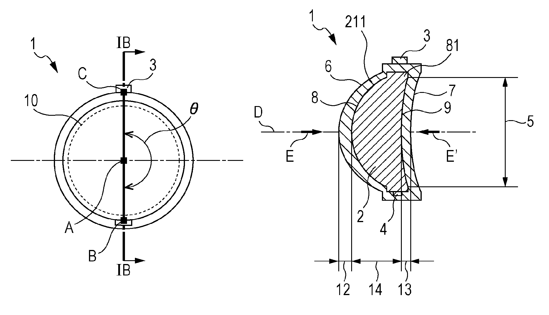
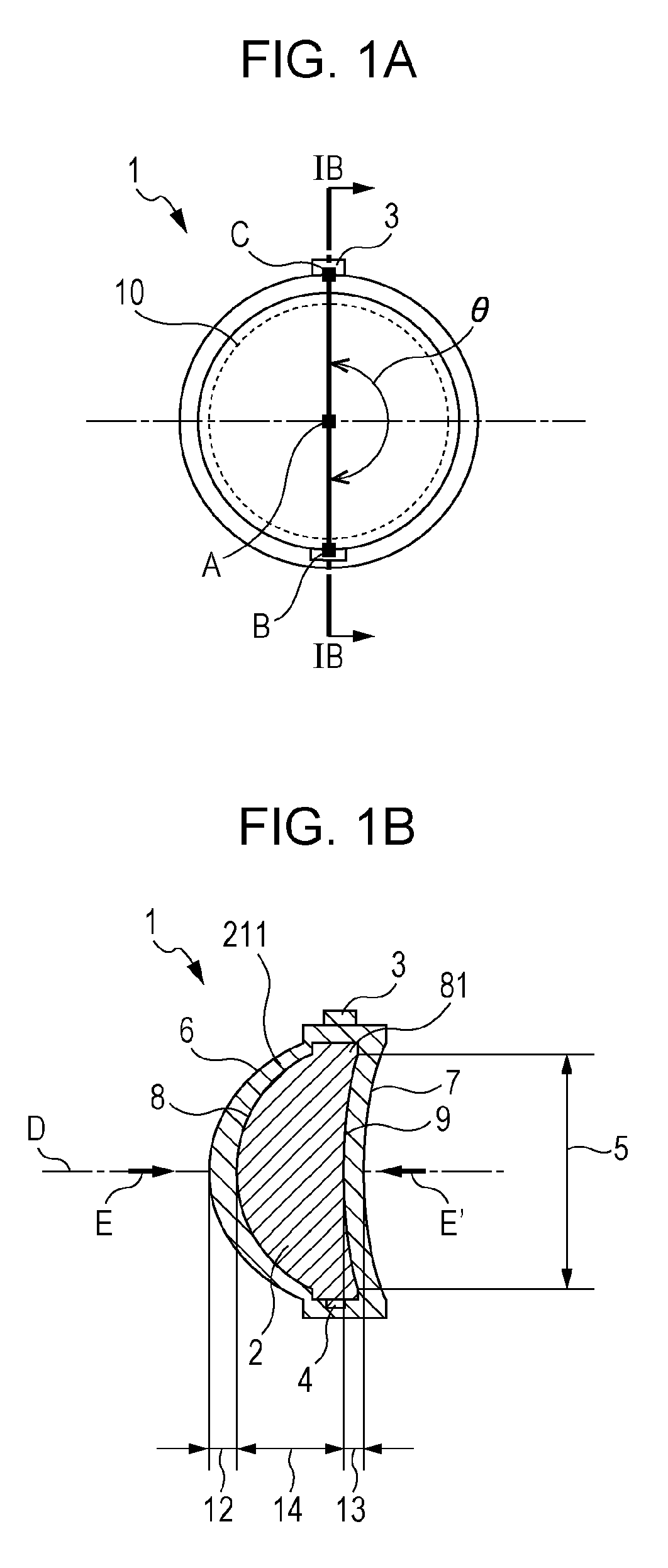
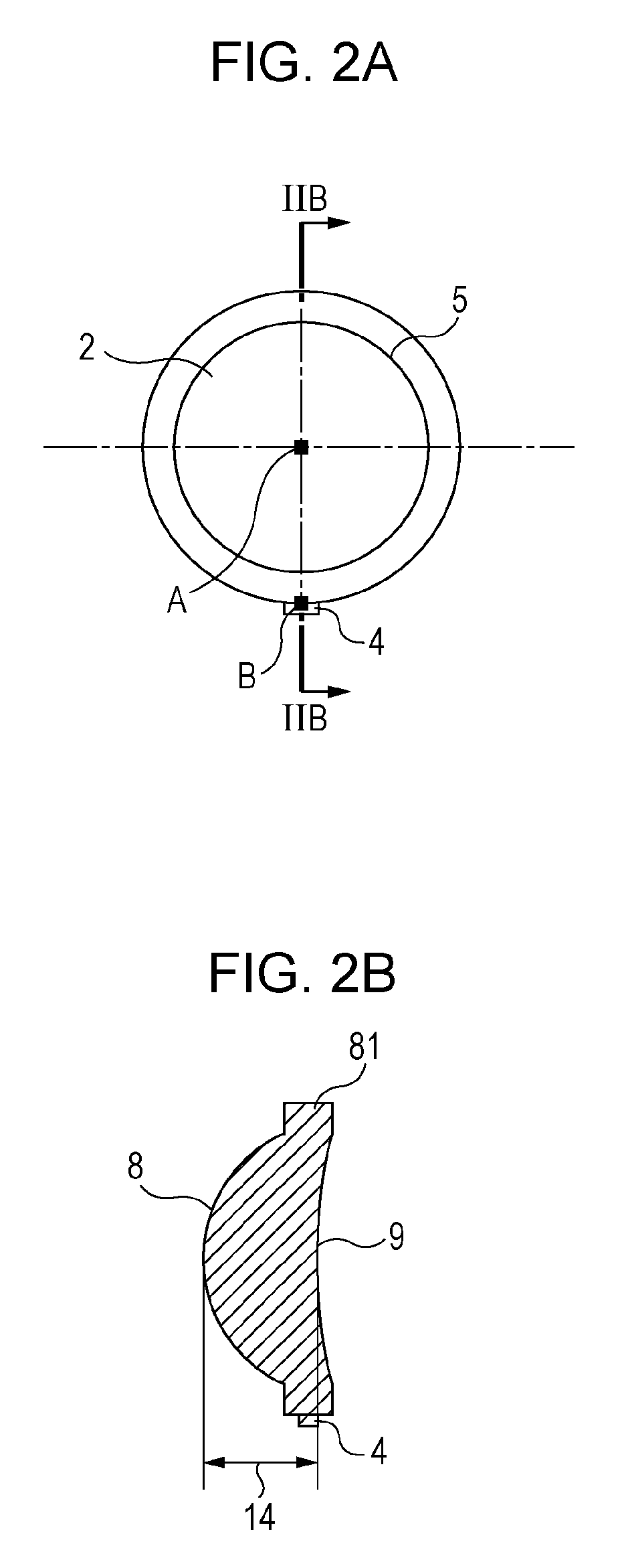
[0023]The plastic optical element according to the present embodiment will now be described with reference to FIGS. 1A and 1B. FIG. 1A is a plan view of the plastic optical element when viewed in a direction along its optical axis (also referred to as the “optical axis direction”) and FIG. 1B is a cross-sectional view thereof taken along the line IB-IB in FIG. 1A. The plastic optical element according to this embodiment includes a core lens 2 and a molded portion 211, serving as a plastic coating, disposed on the core lens 2. FIGS. 2A and 2B are diagrams explaining the core lens 2. FIG. 2A is a plan view of the core lens 2 when viewed in the optical axis direction and FIG. 2B is a cross-sectional view thereof taken along the line IIB-IIB in FIG. 2A. The same parts and components in FIGS. 2A and 2B as those in FIGS. 1A and 1B are designated by the...

second embodiment

[0039]A plastic optical element according to a second embodiment of the present invention and a method of making the same will be described below.

[0040]FIG. 5A is a plan view of the plastic optical element according to this embodiment when viewed in the optical axis direction. FIG. 5B is a cross-sectional view thereof taken along the line VB-VB in FIG. 5A. The same parts and components as those in FIGS. 1A to 2B are designated by the same reference numerals and detailed description thereof is omitted. A rib 15 for divergent coating is provided for the gate corresponding part of the molded portion of the plastic optical element 1 in order to pour plastic for coating into the cavity. In this embodiment, the angle θ formed by the line segment AB and the line segment AC is set in the range of 90 degrees to 180 degrees when viewed in the optical axis direction in a manner similar to the plastic optical element 1 according to the first embodiment. Consequently, the combination of birefrin...

example 1

[0049]In this example, plastic optical elements were made such that the formed angles θ were 180 degrees, 135 degrees, and 90 degrees, and the relationship between birefringence of each plastic optical element and the formed angle θ was determined. As regards measurement of birefringence, the following method was used. Each plastic optical element was disposed between two polarizers (a polarizer and an analyzer), a single-wavelength light beam was applied to the plastic optical element from the side adjacent to the polarizer, the plastic optical element was turned by 360 degrees about its optical axis while the polarizer and the analyzer were held in parallel nicols, and a phase shift was obtained at that time from the angular dependence of the intensity of transmitting light. Measurement was performed using an instrument manufactured by Oji Scientific Instruments.

[0050]First, the plastic optical elements were produced. The plastic optical elements were made using the method describ...


PUM

PropertyMeasurementUnit
anglesaaaaaaaaaa
formed angleaaaaaaaaaa

Abstract

To provide a plastic optical element with reduced birefringence.An angle formed by a line segment that connects a gate corresponding part of a core lens to the center of the core lens and a line segment that connects a gate corresponding part of a molded portion to the center of the core lens is greater than or equal to 90 degrees and is less than or equal to 180 degrees when viewed in a direction along the optical axis of the plastic optical element.

Description

TECHNICAL FIELD[0001]The present invention relates to a plastic optical element included in an optical apparatus, such as a digital camera or a copier, and a method of making the same.BACKGROUND ART[0002]In recent years, there has been growing demand for making a thick optical element by injection molding. An increase in thickness of a plastic optical element leads to an increase in stress caused by the difference in shrinkage on curing between a surface plastic layer that cures first during molding and an inner plastic portion that cures subsequently. Disadvantageously, this causes a vacuum bubble (void) in the optical element or allows inner stress to remain therein. Furthermore, since the time required to cool such a thick optical element in a mold drastically becomes long due to the increase in thickness, a molding cycle markedly increases.[0003]To overcome the above-described disadvantages, PTL 1 discloses a method of making a plastic optical element including a plastic core le...

Claims


Application Information

Patent Timeline
Patent Type & Authority Patents(United States)
IPC IPC(8): G02B7/02G02B3/00B29B11/00B29D11/00
CPCG02B3/00G02B7/02B29D11/0073B29D11/00009
Inventor KOBAYASHI, DAIGOKIKUCHI, WATARU
Owner CANON KK
Why Eureka
Try Eureka